Removed text is struck through; added text is highlighted.
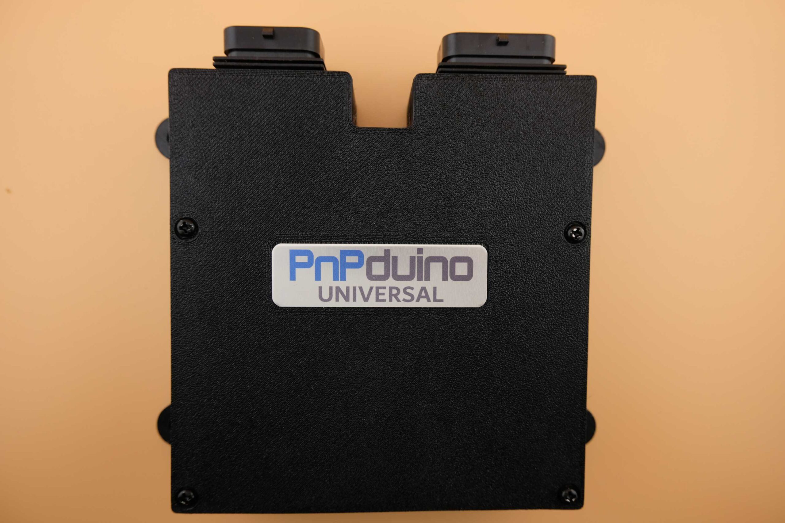
PnPduino Universal is a PnPduino programmable engine-management ECU. Manufacturer product information.
PnPduino Universal. PnPduino manufacturer product photograph, reproduced with permission.
Application and identification
A configurable wire-in ECU that the manufacturer says can operate as a standalone or piggyback and supports engines up to eight cylinders. The manufacturer specifies manual transmission and cable-throttle use.
System and wiring
The input header is a 34-position AMP Superseal 1.0 three-slot connector; the output header is a separate 26-position three-slot connector. Optional components include an internal 4-bar MAP sensor, Bluetooth, VR conditioner, stepper driver and wideband. The ASA/ABS case is not waterproof and the manufacturer says to install it inside the car.
The manufacturer’s model-specific connector schedule is transcribed below. Confirm the hardware revision, optional equipment and calibration before wiring.A complete pin-by-pin ECU connector table has not been verified from the cited product information. Obtain the diagram for the exact model and revision from PnPduino documentation; the vehicle ECU pinout and other PnPduino models must not be assumed interchangeable.
Software and calibration
The product lists TunerStudio and official Speeduino firmware. Verify outputs, sensors and firmware for the actual build and obtain the model-specific pinout before wiring.
See the PnPduino manufacturer index.
Model-specific wiring document
The manufacturer provides a 34-way input and 26-way output connector drawing. Confirm the exact firmware and unit build, and follow the drawn connector orientation. Open the PnPduino pinout document. The separate connector-identification table above is a summary; the full manufacturer-labelled schedule follows below.PnPduino Universal manufacturer connector scheduleTranscribed from the PnPduino PnPduino Universal pinout. Follow the connector drawing in the source and verify the actual build and orientation; the source does not explicitly identify its view as ECU-face or wire-side. Arduino pins are software/board assignments, not connector cavity numbers. A blank manufacturer label is recorded as unlabelled rather than assumed unused.A-plug input — 34 positionsECU pinManufacturer labelManufacturer descriptionArduino pinA1INP4Spare Input 4A11A2INP1Spare Input 1A8A3CLTEngine Coolant TempA4A4TPSThrottle Position SensorA3A5O2Wideband O2 SensorA1A6VR2+VR2+ or Hall Sensor 2D18A7VR1+VR1+ or Hall Sensor 1D19A85V Out5V Out to sensors—A912V In12V Input from Ignition switch—A10INP3Spare Input 3A10A11IATIntake Air TemperatureA5A12PGPower Ground for Wideband—A13PGPower Ground—A14CLUTCHClutch Switch37A15VR2-VR2- / Hall Sensor2 Logic Ground—A16VR1-VR1- / Hall Sensor1 Logic Ground—A17INP5Spare Input 5A6A18GPIGPI for Serial 3 Connection15A19INP2Spare Input 2A9A2012V OutFused 12V Supply(sensors only)—A2112V OutFused 12V Supply(sensors only)—A2212V OutFused 12V Supply(sensors only)—A2312V OutFused 12V Supply(sensors only)—A24VSSVehicle Speed Sensor20A25INP7Spare Input 7A13A26EXTMAPExternal MAP sensorA0A27GPOGPO for Serial 3 Connection14A28FLEXFlex Fuel Sensor2A29HALL4Hall Sensor 43A30GRNDECU Ground—A31GRNDPower Ground—A32GRNDSensor Ground—A33HALL3Hall Sensor 321A34INP6Spare Input 6A12B-plug output — 26 positionsECU pinManufacturer labelManufacturer descriptionArduino pinB1VVTVVT/VVTI or VTEC/VTC terminology11B2IDLE2Idle 2 or Spare High Current 110B3IDLE1Idle 1 for IACV Solenoid9B4INJ4Injector 45B5INJ3Injector 36B6INJ2Injector 27B7INJ1Injector 18B8BOOSTBoost or Spare Hi Current 212B9LC3Low Current Output 328B10LC2Low Current Output 227B11LC1Low Current Output 126B12FANRadiator Fan 124B13Not labelled in source~Not Connected~—B14IGN4Ignition Output 434B15IGN3Ignition Output 333B16LC4Low Current Output 429B17Not labelled in source~Not Connected~—B18FAN2Fan 2 or Spare Low Current Output25B19TACHTachometer Output 5V or 12V22B20IGN1Ignition Output 135B21IGN2Ignition Output 236B22STP-B2Stepper Idle Air Coil B2—B23STP-B1Stepper Idle Air Coil B1—B24STP-A1Stepper Idle Air Coil A1—B25STP-A2Stepper Idle Air Coil A2—B26FUELPFuel Pump or Circuit Opening Relay23The source states that ignition outputs are 5 V, not 12 V; IDLE2 and BOOST can be used as high-current outputs and FAN2 as a low-current output. The manufacturer distinguishes ECU, power and sensor grounds from chassis ground; follow its wiring instructions.The manufacturer provides a 34-way input and 26-way output connector drawing. Confirm the exact firmware and unit build, and follow the drawn connector orientation. Open the PnPduino pinout document. The page’s connector-identification table is not a complete cavity-by-cavity schedule.
Rendered revisions
Open each version to inspect formatting, tables and photographs.
A configurable wire-in ECU that the manufacturer says can operate as a standalone or piggyback and supports engines up to eight cylinders. The manufacturer specifies manual transmission and cable-throttle use.
System and wiring
The input header is a 34-position AMP Superseal 1.0 three-slot connector; the output header is a separate 26-position three-slot connector. Optional components include an internal 4-bar MAP sensor, Bluetooth, VR conditioner, stepper driver and wideband. The ASA/ABS case is not waterproof and the manufacturer says to install it inside the car.
Connector identification
Connector
Manufacturer description
Scope
Input header
34 positions, AMP Superseal 1.0, three-slot
Manufacturer product listing
Output header
26 positions, AMP Superseal 1.0, three-slot
Manufacturer product listing
A complete pin-by-pin ECU connector table has not been verified from the cited product information. Obtain the diagram for the exact model and revision from PnPduino documentation; the vehicle ECU pinout and other PnPduino models must not be assumed interchangeable.
Software and calibration
The product lists TunerStudio and official Speeduino firmware. Verify outputs, sensors and firmware for the actual build and obtain the model-specific pinout before wiring.
The manufacturer provides a 34-way input and 26-way output connector drawing. Confirm the exact firmware and unit build, and follow the drawn connector orientation. Open the PnPduino pinout document. The page’s connector-identification table is not a complete cavity-by-cavity schedule.
A configurable wire-in ECU that the manufacturer says can operate as a standalone or piggyback and supports engines up to eight cylinders. The manufacturer specifies manual transmission and cable-throttle use.
System and wiring
The input header is a 34-position AMP Superseal 1.0 three-slot connector; the output header is a separate 26-position three-slot connector. Optional components include an internal 4-bar MAP sensor, Bluetooth, VR conditioner, stepper driver and wideband. The ASA/ABS case is not waterproof and the manufacturer says to install it inside the car.
Connector identification
Connector
Manufacturer description
Scope
Input header
34 positions, AMP Superseal 1.0, three-slot
Manufacturer product listing
Output header
26 positions, AMP Superseal 1.0, three-slot
Manufacturer product listing
The manufacturer’s model-specific connector schedule is transcribed below. Confirm the hardware revision, optional equipment and calibration before wiring.
Software and calibration
The product lists TunerStudio and official Speeduino firmware. Verify outputs, sensors and firmware for the actual build and obtain the model-specific pinout before wiring.
The manufacturer provides a 34-way input and 26-way output connector drawing. Confirm the exact firmware and unit build, and follow the drawn connector orientation. Open the PnPduino pinout document. The separate connector-identification table above is a summary; the full manufacturer-labelled schedule follows below.
Transcribed from the PnPduino PnPduino Universal pinout. Follow the connector drawing in the source and verify the actual build and orientation; the source does not explicitly identify its view as ECU-face or wire-side. Arduino pins are software/board assignments, not connector cavity numbers. A blank manufacturer label is recorded as unlabelled rather than assumed unused.
A-plug input — 34 positions
ECU pin
Manufacturer label
Manufacturer description
Arduino pin
A1
INP4
Spare Input 4
A11
A2
INP1
Spare Input 1
A8
A3
CLT
Engine Coolant Temp
A4
A4
TPS
Throttle Position Sensor
A3
A5
O2
Wideband O2 Sensor
A1
A6
VR2+
VR2+ or Hall Sensor 2
D18
A7
VR1+
VR1+ or Hall Sensor 1
D19
A8
5V Out
5V Out to sensors
—
A9
12V In
12V Input from Ignition switch
—
A10
INP3
Spare Input 3
A10
A11
IAT
Intake Air Temperature
A5
A12
PG
Power Ground for Wideband
—
A13
PG
Power Ground
—
A14
CLUTCH
Clutch Switch
37
A15
VR2-
VR2- / Hall Sensor2 Logic Ground
—
A16
VR1-
VR1- / Hall Sensor1 Logic Ground
—
A17
INP5
Spare Input 5
A6
A18
GPI
GPI for Serial 3 Connection
15
A19
INP2
Spare Input 2
A9
A20
12V Out
Fused 12V Supply(sensors only)
—
A21
12V Out
Fused 12V Supply(sensors only)
—
A22
12V Out
Fused 12V Supply(sensors only)
—
A23
12V Out
Fused 12V Supply(sensors only)
—
A24
VSS
Vehicle Speed Sensor
20
A25
INP7
Spare Input 7
A13
A26
EXTMAP
External MAP sensor
A0
A27
GPO
GPO for Serial 3 Connection
14
A28
FLEX
Flex Fuel Sensor
2
A29
HALL4
Hall Sensor 4
3
A30
GRND
ECU Ground
—
A31
GRND
Power Ground
—
A32
GRND
Sensor Ground
—
A33
HALL3
Hall Sensor 3
21
A34
INP6
Spare Input 6
A12
B-plug output — 26 positions
ECU pin
Manufacturer label
Manufacturer description
Arduino pin
B1
VVT
VVT/VVTI or VTEC/VTC terminology
11
B2
IDLE2
Idle 2 or Spare High Current 1
10
B3
IDLE1
Idle 1 for IACV Solenoid
9
B4
INJ4
Injector 4
5
B5
INJ3
Injector 3
6
B6
INJ2
Injector 2
7
B7
INJ1
Injector 1
8
B8
BOOST
Boost or Spare Hi Current 2
12
B9
LC3
Low Current Output 3
28
B10
LC2
Low Current Output 2
27
B11
LC1
Low Current Output 1
26
B12
FAN
Radiator Fan 1
24
B13
Not labelled in source
~Not Connected~
—
B14
IGN4
Ignition Output 4
34
B15
IGN3
Ignition Output 3
33
B16
LC4
Low Current Output 4
29
B17
Not labelled in source
~Not Connected~
—
B18
FAN2
Fan 2 or Spare Low Current Output
25
B19
TACH
Tachometer Output 5V or 12V
22
B20
IGN1
Ignition Output 1
35
B21
IGN2
Ignition Output 2
36
B22
STP-B2
Stepper Idle Air Coil B2
—
B23
STP-B1
Stepper Idle Air Coil B1
—
B24
STP-A1
Stepper Idle Air Coil A1
—
B25
STP-A2
Stepper Idle Air Coil A2
—
B26
FUELP
Fuel Pump or Circuit Opening Relay
23
The source states that ignition outputs are 5 V, not 12 V; IDLE2 and BOOST can be used as high-current outputs and FAN2 as a low-current output. The manufacturer distinguishes ECU, power and sensor grounds from chassis ground; follow its wiring instructions.