VBOX Video HD1 combines a camera, GNSS and vehicle-data recorder for circuit analysis. Features and supplied accessories depend on the exact kit.
Specifications

HD1 integrates a single video camera, GNSS antenna and recorder in a compact vehicle-powered unit. It records 1920 × 1080 video at 30 frames per second and 25 Hz multi-constellation GNSS data, with an overlay including lap times, position, speed and g-force. It has two isolated CAN interfaces supporting CAN 2.0 and CAN FD, and can log up to 80 CAN channels. Speed-triggered recording, an HDMI output and optional predictive lap timing display are available. Circuit Tools 3 is included. [2] [1]
RACELOGIC provides Circuit Tools analysis and configurable graphical overlays; see HD1 product information.
Connectors and pinouts

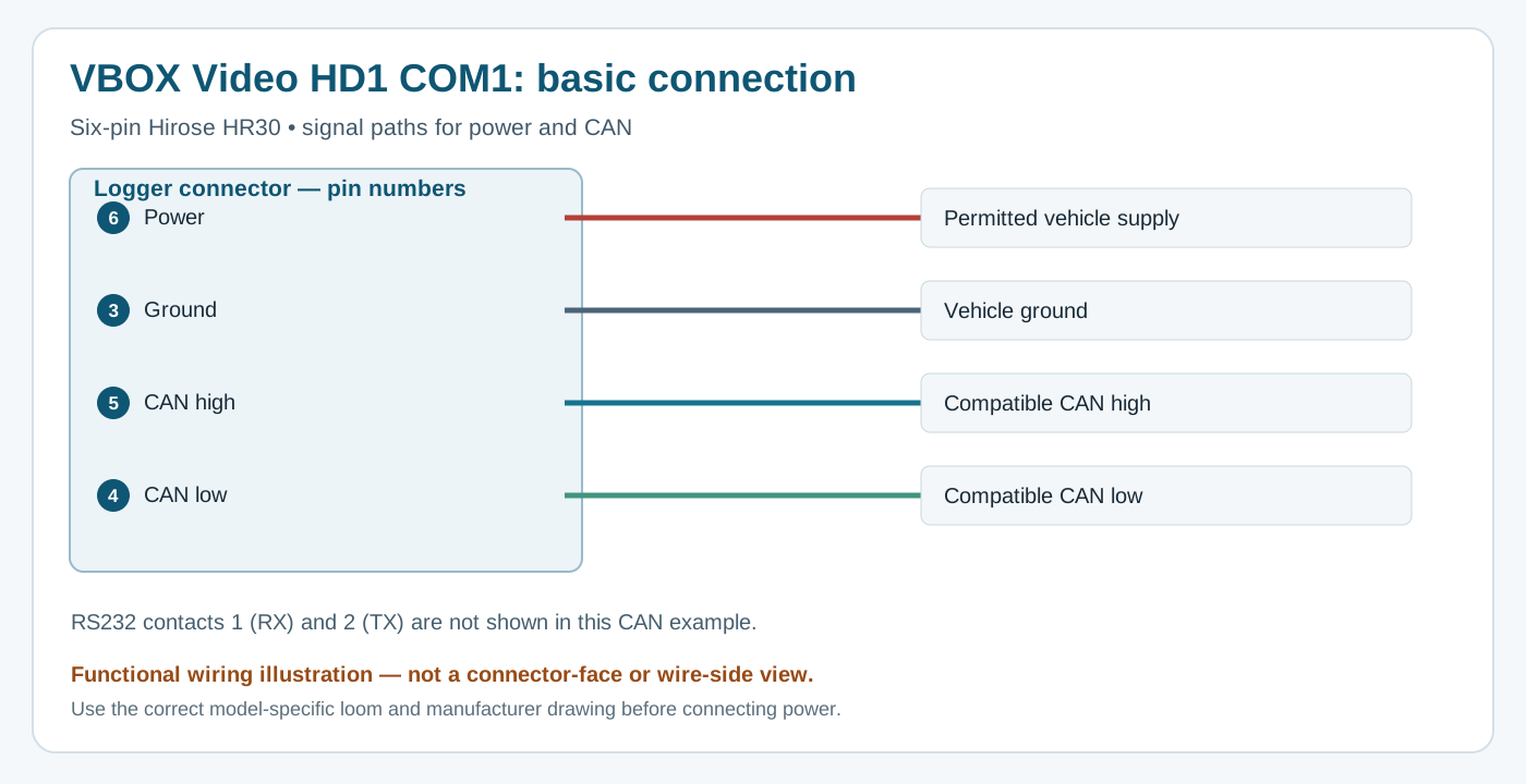
RACELOGIC’s HD1 pinout lists the same six pin assignments for both power/communications HR30 connectors, with the OLED display supported only on COM1. The separate hardware overview identifies COM1 with CAN 1 and the second power/communications connector with CAN 2, while the pinout page describes both as CAN 1. Confirm the individual bus selection and hardware with RACELOGIC before wiring; the shared pin labels alone do not resolve that documentation conflict.
| Pin | HD1 six-pin Hirose HR30 function |
|---|---|
| 1 | RS232 RX |
| 2 | RS232 TX |
| 3 | Ground |
| 4 | CAN low |
| 5 | CAN high |
| 6 | Power |
The same pinout lists the separate three-pin external microphone connector: 1 audio in, 2 mic bias, 3 audio ground. The hardware overview specifies 6–18 V DC supply and separate GNSS antenna and micro-HDMI connections; HDMI output needs an external recorder or streaming encoder for remote video.
For the manufacturer's HD1 installation harness, red is nominal +12 V, blue ground, yellow CAN high and green CAN low. Those colours apply to that harness only; verify the cable supplied. The manufacturer recommends ignition-switched power and cautions against connection to a jump-start lead or charger under load.
Consult the linked manufacturer drawings for connector face and orientation, verify the actual hardware and cable before connection, and check the ECU protocol, CAN bitrate and the vehicle's available data. Related: RACELOGIC VBOX manufacturer guide.
Data analysis software
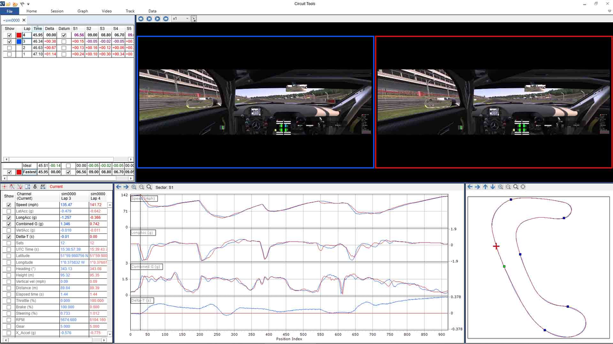
Copy the recorded data and associated video to a computer and open the session in Circuit Tools to compare laps, traces and synchronised video. The manufacturer lists Circuit Tools for analysis of this product. Manufacturer product documentation.
Download Circuit Tools from RACELOGIC. The manufacturer offers Windows, macOS and iOS editions; check the product, file and operating-system compatibility for the edition used. See the RACELOGIC manufacturer guide for analysis workflow and edition differences.