Removed text is struck through; added text is highlighted.
Earlier programmable injection and ignition controller; the Portuguese manufacturer manual describes distributor ignition, injector wiring, auxiliary outputs and model-specific trigger arrangements. FuelTech primary source.
Identification and wiring
Record the precise controller and hardware before wiring. The original installation document must be matched to the unit and connector; no pin assignments are inferred from later FuelTech models. FuelTech Portuguese manuals index · English manuals.
See FuelTech ECU family. Sources reviewed 17 November 2026.
24-way main harness connector
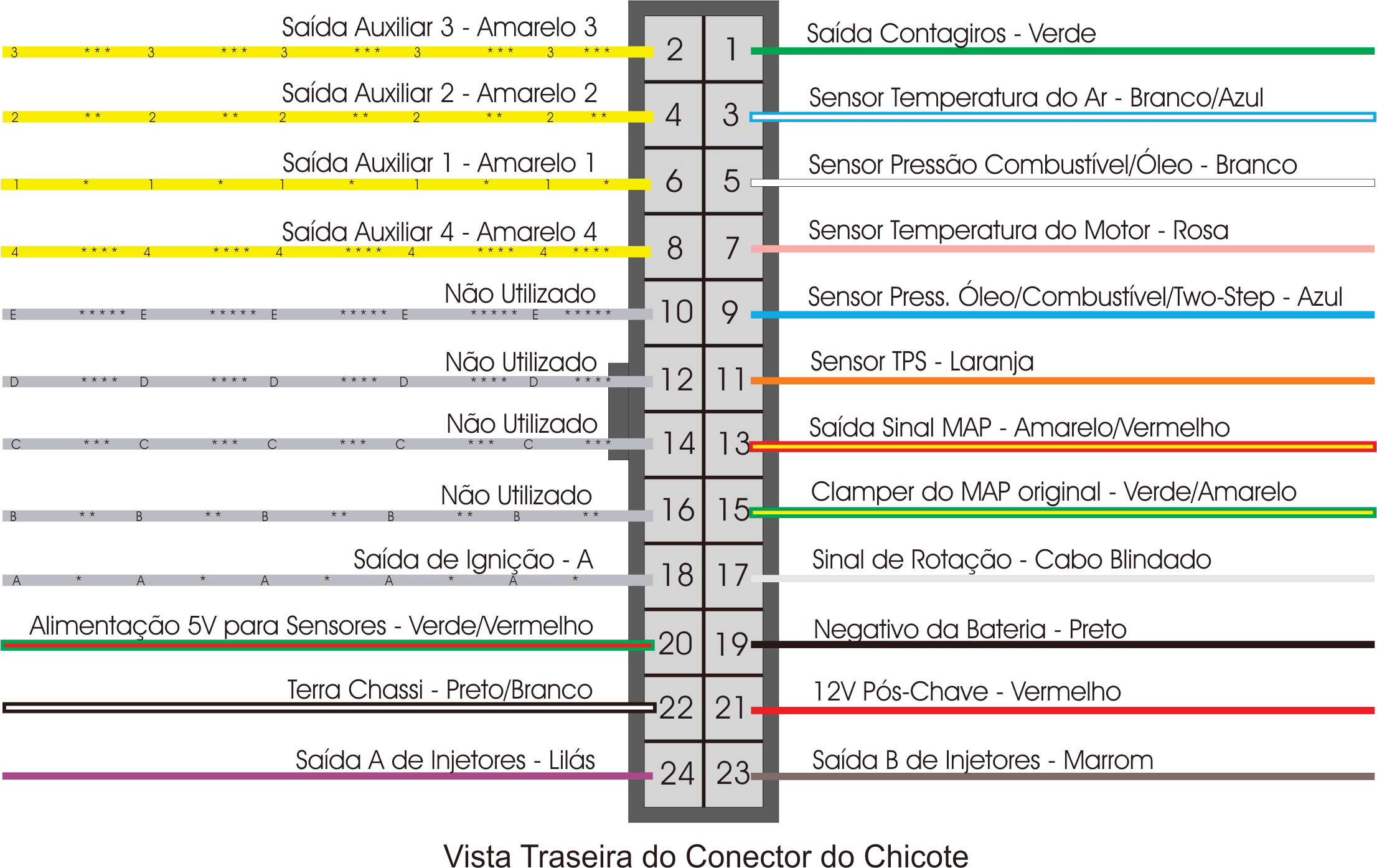
Translated from the FuelTech FT200 installation manual in Portuguese, section 4.1. Establish orientation from the source and match the ECU revision. Ignition outputs B–E are marked unused on the FT200. The FT200 grounding instructions differ from those of some later FuelTech ECUs; consult its original documentation rather than transferring a later model’s scheme.
PinFunction and harness wire1Tachometer output (green)2Auxiliary output 3 (yellow 3)3Intake air temperature input (white/blue)4Auxiliary output 2 (yellow 2)5Fuel or oil pressure input (white)6Auxiliary output 1 (yellow 1)7Coolant temperature input (pink)8Auxiliary output 4 (yellow 4)9Fuel/oil pressure or two-step input (blue)10Not used (gray E)11Throttle position signal (orange)12Not used (gray D)13MAP signal output (yellow/red)14Not used (gray C)15Original MAP/MAF signal clamper (green/yellow)16Not used (gray B)17RPM signal input (shielded cable)18Ignition output A (gray A)19Battery negative / signal ground (black)205 V sensor supply (green/red)21Switched 12 V supply (red)22Chassis power ground (black/white)23Fuel injector bank B negative (brown)24Fuel injector bank A negative (purple)
FuelTech FT200 24-way harness connector, rear (wire-side) view. Diagram from FuelTech FT200 installation manual, page 8; reproduced with permission. The diagram is in Portuguese; the table above translates the assignments.
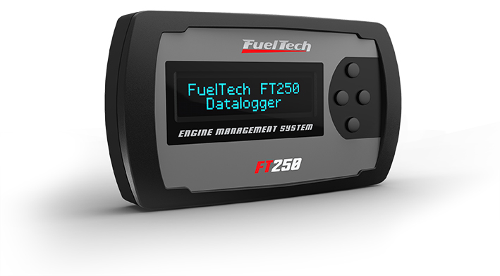
FuelTech FT250 shown as a related FT-family illustration; it is not an FT200. Product photograph from the FuelTech manufacturer media kit, reproduced with permission.
Rendered revisions
Open each version to inspect formatting, tables and photographs.
Revision 3: FuelTech FT200
Earlier programmable injection and ignition controller; the Portuguese manufacturer manual describes distributor ignition, injector wiring, auxiliary outputs and model-specific trigger arrangements. FuelTech primary source.
Identification and wiring
Record the precise controller and hardware before wiring. The original installation document must be matched to the unit and connector; no pin assignments are inferred from later FuelTech models. FuelTech Portuguese manuals index · English manuals.
Translated from the FuelTech FT200 installation manual in Portuguese, section 4.1. Establish orientation from the source and match the ECU revision. Ignition outputs B–E are marked unused on the FT200. The FT200 grounding instructions differ from those of some later FuelTech ECUs; consult its original documentation rather than transferring a later model’s scheme.
Pin
Function and harness wire
1
Tachometer output (green)
2
Auxiliary output 3 (yellow 3)
3
Intake air temperature input (white/blue)
4
Auxiliary output 2 (yellow 2)
5
Fuel or oil pressure input (white)
6
Auxiliary output 1 (yellow 1)
7
Coolant temperature input (pink)
8
Auxiliary output 4 (yellow 4)
9
Fuel/oil pressure or two-step input (blue)
10
Not used (gray E)
11
Throttle position signal (orange)
12
Not used (gray D)
13
MAP signal output (yellow/red)
14
Not used (gray C)
15
Original MAP/MAF signal clamper (green/yellow)
16
Not used (gray B)
17
RPM signal input (shielded cable)
18
Ignition output A (gray A)
19
Battery negative / signal ground (black)
20
5 V sensor supply (green/red)
21
Switched 12 V supply (red)
22
Chassis power ground (black/white)
23
Fuel injector bank B negative (brown)
24
Fuel injector bank A negative (purple)
FuelTech FT200 24-way harness connector, rear (wire-side) view. Diagram from FuelTech FT200 installation manual, page 8; reproduced with permission. The diagram is in Portuguese; the table above translates the assignments.FuelTech FT250 shown as a related FT-family illustration; it is not an FT200. Product photograph from the FuelTech manufacturer media kit, reproduced with permission.Revision 3: FuelTech FT200
Earlier programmable injection and ignition controller; the Portuguese manufacturer manual describes distributor ignition, injector wiring, auxiliary outputs and model-specific trigger arrangements. FuelTech primary source.
Identification and wiring
Record the precise controller and hardware before wiring. The original installation document must be matched to the unit and connector; no pin assignments are inferred from later FuelTech models. FuelTech Portuguese manuals index · English manuals.
Translated from the FuelTech FT200 installation manual in Portuguese, section 4.1. Establish orientation from the source and match the ECU revision. Ignition outputs B–E are marked unused on the FT200. The FT200 grounding instructions differ from those of some later FuelTech ECUs; consult its original documentation rather than transferring a later model’s scheme.
Pin
Function and harness wire
1
Tachometer output (green)
2
Auxiliary output 3 (yellow 3)
3
Intake air temperature input (white/blue)
4
Auxiliary output 2 (yellow 2)
5
Fuel or oil pressure input (white)
6
Auxiliary output 1 (yellow 1)
7
Coolant temperature input (pink)
8
Auxiliary output 4 (yellow 4)
9
Fuel/oil pressure or two-step input (blue)
10
Not used (gray E)
11
Throttle position signal (orange)
12
Not used (gray D)
13
MAP signal output (yellow/red)
14
Not used (gray C)
15
Original MAP/MAF signal clamper (green/yellow)
16
Not used (gray B)
17
RPM signal input (shielded cable)
18
Ignition output A (gray A)
19
Battery negative / signal ground (black)
20
5 V sensor supply (green/red)
21
Switched 12 V supply (red)
22
Chassis power ground (black/white)
23
Fuel injector bank B negative (brown)
24
Fuel injector bank A negative (purple)
FuelTech FT200 24-way harness connector, rear (wire-side) view. Diagram from FuelTech FT200 installation manual, page 8; reproduced with permission. The diagram is in Portuguese; the table above translates the assignments.FuelTech FT250 shown as a related FT-family illustration; it is not an FT200. Product photograph from the FuelTech manufacturer media kit, reproduced with permission.