PEREK supplies dynamometer data acquisition, controllers and brake interfaces for new builds and retrofits. Its systems can be configured for engine, rolling-road and hub installations; the controller and power electronics must be matched to the existing dynamometer hardware. See Dynamometers and the manufacturers directory.
History and role
Ronald Perek states that he founded PEREK in 2019 after mechatronics and electronics work at ECUMASTER. The company describes its work as dyno measurement and control, including upgrades of existing equipment from other makers. A conversion can retain the original frame and brake while changing controller components; the dyno's name does not necessarily identify the controller fitted today. PEREK: company and applications.
Systems and applications
PEREK describes its controller system for inertial and braked engine, chassis, hub and power-take-off dynos. Its peripheral guide specifies different speed-sensor counts for different layouts and identifies the separate absorber, load cell and brake supply needed for an absorption dyno. PEREK lists partner builders for complete machines; these are distinct companies, not PEREK dyno model names.
Controller and brake-interface models
- DC1E4: an earlier controller identified by PEREK in documented retrofit examples, including a Bosch FLA206 upgrade.
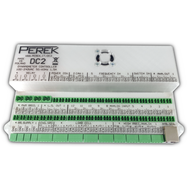
- DC2: an integrated computer and controller; the maker lists support for unsynchronised 4WD chassis and 4WD hub systems with appropriate peripherals.
- DC2L: a lower-specification DC2-series variant for less complex applications, including mechanically synchronised 4WD chassis systems.
- BD3.1: an eddy-current brake power interface. Its electrical supply and brake compatibility must be checked for the installation.
The DC2 specification distinguishes the two variants and identifies the DC2 as a development of the earlier DC1E4. Dyno2 software supplies test display, recording and analysis; exact operating modes depend on the complete configured system.
Checking a retrofit
Record brake model, torque and speed limits, controller, software, power supply, sensor scaling, calibration and interlock arrangements. A capable controller cannot make an absorber motor a shaft or operate safely beyond its own cooling and mechanical limits. See dynamometer control systems.
Details are based on the linked company documentation checked 17 November 2026; verify present configurations and support with the supplier.
DC2 and DC2L input and output comparison
The manufacturer's DC2 series specification describes an integrated computer and real-time microcontroller. It provides the following model-specific counts; sensor, actuator and brake-interface suitability must still be checked for the exact installation.
| Feature | DC2L | DC2 |
|---|---|---|
| Layouts | Engine, motorcycle and 2WD chassis; 4WD chassis when axles are mechanically synchronised. | Engine, chassis and 2WD/4WD hub; 4WD chassis with or without mechanical axle synchronisation. |
| Frequency / speed inputs | One frequency input plus one multisensor engine-speed input. | Five frequency inputs plus one multisensor engine-speed input. |
| Load cell inputs | One. | Four. |
| Analogue inputs | One fast 0–5 V and four high-precision inputs with thermocouple support. | Twelve fast 0–5 V and eight high-precision inputs with thermocouple support. |
| Brake/control outputs | One analogue output and two low-side PWM outputs. | Four analogue outputs, four low-side and four high-side PWM outputs; additional switching and relay outputs. |
| CAN interfaces | One. | Two. |
Outputs can control compatible external power electronics or actuators using suitable PWM, 0–10 V or CAN commands; PEREK also specifies direct PWM up to 3 A where applicable. A high-current eddy-current absorber generally needs a matched brake power supply. The sensor requirement rises with independently rotating shafts: the peripheral guide lists two speed sensors for a 2WD hub setup and four for a 4WD hub setup. Electronic synchronisation has limits and must suit the vehicle and dyno.
BD3 and BD3.1 eddy-brake power supplies
The BD3/BD3.1 manual describes a separate mains-supplied eddy-current interface with closed-loop brake-current control, fast demagnetisation and CAN diagnostics such as current and power-stage temperature. PEREK lists single- or three-phase supply possibilities and different current ratings and duty limits; match the exact variant, supply, cooling and absorber coil rating. The brake and its power stage, not the DC controller alone, set the available loading.
BD3.1 differs from BD3 in its cooling and power-supply arrangement and removes the earlier PWM input; do not assume both variants accept the same control signals. The manual describes CAN control for BD3.1. Observe the manufacturer's isolation, capacitor-discharge, installation and emergency procedures.
Dyno2 control, logging and automation
Dyno2 supports calibration tools, graphs and run comparison, channels from compatible CAN and OBD equipment, configurable reports and CSV export. PEREK lists modes including RPM lock, constant power, RPM limit and test sequences; availability and usable control depend on the installed hardware and configuration. The run-tab guide also describes manual absorber demand and speed and acceleration control.
In a documented control architecture, the speed loop compares measured and desired speed; a torque loop can then use load-cell feedback to request brake output. A separate position loop can use analogue feedback for a water valve or throttle actuator. PEREK states that these real-time control loops run at 1,000 Hz, whereas an optional software function PID runs at 100 Hz; these are loop update rates, not a guarantee of complete machine response or accuracy. See control-loop documentation.
The manufacturer describes configurable CAN channels, remote-control inputs and test sequences. These features require correct signal, actuator and safety configuration. Dyno2 remote control; retrofitting guidance.