Removed text is struck through; added text is highlighted.
Electromotive TEC-1 is a model in the Total Engine Control family. Early TEC engine-management system covered with TEC-II in Electromotive’s legacy installation and calibration manual. Manufacturer source.
Identification and software
Identify the exact model, serial, firmware and ignition-driver configuration before using a calibration or connecting a loom. WinTEC versions and hardware vary; the Electromotive manual archive separates the generations.
Wiring and pinout
Consult the model-specific manufacturer source and technical archive for the matching connector, firing order, ECU earths, injector drivers and ignition connections. Do not transfer TECgt200 or TECs200 positions to earlier TEC units. Where a complete exact-model pinout has not been verified, use the manufacturer documentation and verify the actual part number.
Availability
As of 17 November 2026, the manufacturer states it is not selling or repairing products. Electromotive notice. See the Electromotive family reference.
Illustrated TEC-I terminal schedules
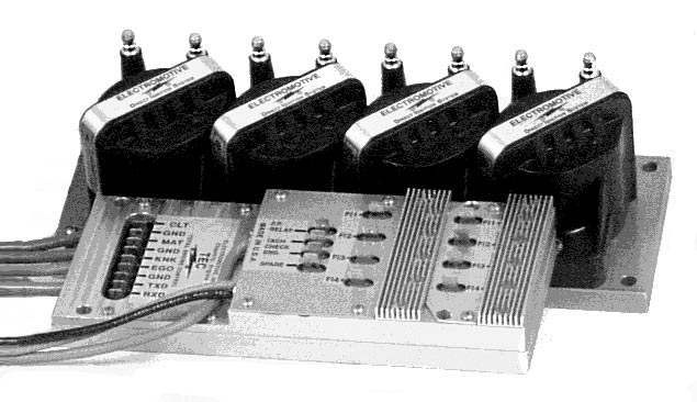
The printed labels below are taken from the Electromotive's TEC installation manual. They identify the terminals shown in the drawings; they are not manufacturer-numbered connector cavities. Other plugs and wiring vary with the actual ECU, injector drivers and engine. Consult the complete drawing and check the markings on the unit. The TEC-I fuel-pump relay terminal is a ground-switching output; it differs from the TEC-II output described in the manual.
The manual shows different configurations on pages 41–43. The six-cylinder dual-plug drawing and the twelve-cylinder/three-rotor drawings do not show identical terminal-block layouts: the knock and oxygen positions exchange order and the latter drawings include two unlabelled positions. The lists are in drawing order from top to bottom, not pin numbers.
Six-cylinder dual-plug sensor and communication terminals, page 41
Marking or leadDocumented functionCLTCoolant temperature sensorGNDGround adjacent to CLTMATManifold air temperature sensorGNDGround adjacent to MATKNKKnock sensor inputEGOExhaust-gas oxygen sensor signalGNDGroundTXDTransmit dataRXDReceive data
Twelve-cylinder and three-rotor sensor and communication terminals, pages 42–43
Marking or leadDocumented functionCLTCoolant temperature sensorGNDGround adjacent to CLTMATManifold air temperature sensorGNDGround adjacent to MATEGOExhaust-gas oxygen sensor signalKNKKnock sensor inputUnlabelledNo assignment given on drawingUnlabelledNo assignment given on drawingGNDGroundTXDTransmit dataRXDReceive data
Adjacent output terminals
Marking or leadDocumented functionF.P. RELAYFuel-pump relay control; TEC-I uses a pull-to-ground outputTACHTachometer outputCHECK ENG.Check-engine light outputSPAREOptional general-purpose output; build-dependent
Illustrated FI injector-driver markings
Marking or leadDocumented functionFI1Injector-driver terminal for coil A event; repeated on second driver bankFI2Injector-driver terminal for coil B event; repeated on second driver bankFI3Injector-driver terminal for coil C event; repeated on second driver bank
Illustrated power leads
Marking or leadDocumented functionECU red (+) leadPositive supply, shown through main-power relayECU black (−) leadGroundDirect-fire unit red (+) leadPositive supply, shown through main-power relayDirect-fire unit black (−) leadGround
The drawing shows an optional second three-driver bank. FI1–FI3 are repeated on the two banks; the manual relates them to the A–C coil events and explains how configurations use the additional drivers. Do not assume that an unlabelled terminal is unused or transplant the later TEC-II numbered header.
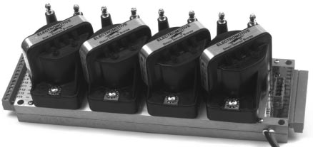
TEC R-88, a TEC-I family configuration; individual TEC-I configurations differ. Image from the Electromotive TEC installation manual, page 5; reproduced with permission.TEC-II eight-cylinder controller shown as a related family illustration; the earlier TEC-I differs. Image: Electromotive, reproduced with permission.
Rendered revisions
Open each version to inspect formatting, tables and photographs.
Revision 3: Electromotive TEC-1
Electromotive TEC-1 is a model in the Total Engine Control family. Early TEC engine-management system covered with TEC-II in Electromotive’s legacy installation and calibration manual. Manufacturer source.
Identification and software
Identify the exact model, serial, firmware and ignition-driver configuration before using a calibration or connecting a loom. WinTEC versions and hardware vary; the Electromotive manual archive separates the generations.
Wiring and pinout
Consult the model-specific manufacturer source and technical archive for the matching connector, firing order, ECU earths, injector drivers and ignition connections. Do not transfer TECgt200 or TECs200 positions to earlier TEC units. Where a complete exact-model pinout has not been verified, use the manufacturer documentation and verify the actual part number.
The printed labels below are taken from the Electromotive's TEC installation manual. They identify the terminals shown in the drawings; they are not manufacturer-numbered connector cavities. Other plugs and wiring vary with the actual ECU, injector drivers and engine. Consult the complete drawing and check the markings on the unit. The TEC-I fuel-pump relay terminal is a ground-switching output; it differs from the TEC-II output described in the manual.
The manual shows different configurations on pages 41–43. The six-cylinder dual-plug drawing and the twelve-cylinder/three-rotor drawings do not show identical terminal-block layouts: the knock and oxygen positions exchange order and the latter drawings include two unlabelled positions. The lists are in drawing order from top to bottom, not pin numbers.
Six-cylinder dual-plug sensor and communication terminals, page 41
Marking or lead
Documented function
CLT
Coolant temperature sensor
GND
Ground adjacent to CLT
MAT
Manifold air temperature sensor
GND
Ground adjacent to MAT
KNK
Knock sensor input
EGO
Exhaust-gas oxygen sensor signal
GND
Ground
TXD
Transmit data
RXD
Receive data
Twelve-cylinder and three-rotor sensor and communication terminals, pages 42–43
Marking or lead
Documented function
CLT
Coolant temperature sensor
GND
Ground adjacent to CLT
MAT
Manifold air temperature sensor
GND
Ground adjacent to MAT
EGO
Exhaust-gas oxygen sensor signal
KNK
Knock sensor input
Unlabelled
No assignment given on drawing
Unlabelled
No assignment given on drawing
GND
Ground
TXD
Transmit data
RXD
Receive data
Adjacent output terminals
Marking or lead
Documented function
F.P. RELAY
Fuel-pump relay control; TEC-I uses a pull-to-ground output
TACH
Tachometer output
CHECK ENG.
Check-engine light output
SPARE
Optional general-purpose output; build-dependent
Illustrated FI injector-driver markings
Marking or lead
Documented function
FI1
Injector-driver terminal for coil A event; repeated on second driver bank
FI2
Injector-driver terminal for coil B event; repeated on second driver bank
FI3
Injector-driver terminal for coil C event; repeated on second driver bank
Illustrated power leads
Marking or lead
Documented function
ECU red (+) lead
Positive supply, shown through main-power relay
ECU black (−) lead
Ground
Direct-fire unit red (+) lead
Positive supply, shown through main-power relay
Direct-fire unit black (−) lead
Ground
The drawing shows an optional second three-driver bank. FI1–FI3 are repeated on the two banks; the manual relates them to the A–C coil events and explains how configurations use the additional drivers. Do not assume that an unlabelled terminal is unused or transplant the later TEC-II numbered header.
TEC-II eight-cylinder controller shown as a related family illustration; the earlier TEC-I differs. Image: Electromotive, reproduced with permission.Revision 4: Electromotive TEC-1
Electromotive TEC-1 is a model in the Total Engine Control family. Early TEC engine-management system covered with TEC-II in Electromotive’s legacy installation and calibration manual. Manufacturer source.
Identification and software
Identify the exact model, serial, firmware and ignition-driver configuration before using a calibration or connecting a loom. WinTEC versions and hardware vary; the Electromotive manual archive separates the generations.
Wiring and pinout
Consult the model-specific manufacturer source and technical archive for the matching connector, firing order, ECU earths, injector drivers and ignition connections. Do not transfer TECgt200 or TECs200 positions to earlier TEC units. Where a complete exact-model pinout has not been verified, use the manufacturer documentation and verify the actual part number.
The printed labels below are taken from the Electromotive's TEC installation manual. They identify the terminals shown in the drawings; they are not manufacturer-numbered connector cavities. Other plugs and wiring vary with the actual ECU, injector drivers and engine. Consult the complete drawing and check the markings on the unit. The TEC-I fuel-pump relay terminal is a ground-switching output; it differs from the TEC-II output described in the manual.
The manual shows different configurations on pages 41–43. The six-cylinder dual-plug drawing and the twelve-cylinder/three-rotor drawings do not show identical terminal-block layouts: the knock and oxygen positions exchange order and the latter drawings include two unlabelled positions. The lists are in drawing order from top to bottom, not pin numbers.
Six-cylinder dual-plug sensor and communication terminals, page 41
Marking or lead
Documented function
CLT
Coolant temperature sensor
GND
Ground adjacent to CLT
MAT
Manifold air temperature sensor
GND
Ground adjacent to MAT
KNK
Knock sensor input
EGO
Exhaust-gas oxygen sensor signal
GND
Ground
TXD
Transmit data
RXD
Receive data
Twelve-cylinder and three-rotor sensor and communication terminals, pages 42–43
Marking or lead
Documented function
CLT
Coolant temperature sensor
GND
Ground adjacent to CLT
MAT
Manifold air temperature sensor
GND
Ground adjacent to MAT
EGO
Exhaust-gas oxygen sensor signal
KNK
Knock sensor input
Unlabelled
No assignment given on drawing
Unlabelled
No assignment given on drawing
GND
Ground
TXD
Transmit data
RXD
Receive data
Adjacent output terminals
Marking or lead
Documented function
F.P. RELAY
Fuel-pump relay control; TEC-I uses a pull-to-ground output
TACH
Tachometer output
CHECK ENG.
Check-engine light output
SPARE
Optional general-purpose output; build-dependent
Illustrated FI injector-driver markings
Marking or lead
Documented function
FI1
Injector-driver terminal for coil A event; repeated on second driver bank
FI2
Injector-driver terminal for coil B event; repeated on second driver bank
FI3
Injector-driver terminal for coil C event; repeated on second driver bank
Illustrated power leads
Marking or lead
Documented function
ECU red (+) lead
Positive supply, shown through main-power relay
ECU black (−) lead
Ground
Direct-fire unit red (+) lead
Positive supply, shown through main-power relay
Direct-fire unit black (−) lead
Ground
The drawing shows an optional second three-driver bank. FI1–FI3 are repeated on the two banks; the manual relates them to the A–C coil events and explains how configurations use the additional drivers. Do not assume that an unlabelled terminal is unused or transplant the later TEC-II numbered header.
TEC R-88, a TEC-I family configuration; individual TEC-I configurations differ. Image from the Electromotive TEC installation manual, page 5; reproduced with permission.