Removed text is struck through; added text is highlighted.
Adaptronic eSel010 is a Select-series vehicle plug-in programmable engine-management ECU. The surviving manufacturer guide identifies the intended application as Nissan S14 Silvia / 200SX SR20DET and S13 CA18DET applications. Adaptronic eSel010 application and installation guide.
Identification and application
Confirm the case label and part number, original ECU and loom connector, engine, market and any vehicle-specific equipment against the guide before purchase or installation. Vehicle wiring can vary, and a shared plug shape does not establish pin compatibility.
Software and installation
The Select family uses Adaptronic WARI software, which is listed in Haltech’s legacy Adaptronic downloads archive. Use the matching eSel010 guide and application-specific basemap; the guide documents installation, configuration and pin references. A plug-in ECU still requires configuration and tuning for the actual engine and equipment.
Wiring and pinout
The manufacturer eSel010 guide contains the model and application-specific connector information. Positions and functions can change by application, and factory function and Adaptronic function are separate columns in the guide. The manufacturer connector table is transcribed below; verify the source and viewpoint before use.
Support and sources
Haltech states that Adaptronic operations ended in 2022. Refer to its Adaptronic notice and archived guides, and confirm current support and compatibility for used hardware. A verified product photograph for this exact part has not yet been added.
Adaptronic manufacturer index
Manufacturer connector schedules
Transcribed from the Adaptronic eSel010 installation guide. Compare the application-specific descriptions, and configure the internal jumper for the relevant ignition output. The source gives numbering from the loom side, looking into the ECU. In the vehicle-connector tables, “NC” is the source's designation for no factory loom connection; a blank Adaptronic entry means no connection to the Adaptronic ECU. A dash in the table reproduces a blank source field.
Factory pinFactory functionAdaptronic functionComments101Injector for Cylinder 1Injector Output 3—102Purge Valve——103Injector for Cylinder 3Injector Output 4—104NC——105NC——106Idle Control Valve (CA18)Aux output 2—107GroundPower Ground—108GroundPower Ground—109Constant PowerConst 12VStraight from battery via fuse110Injector for Cylinder 2Injector Output 2—111NC——112Injector for Cylinder 4Injector Output 1—113Valve Timing Control solenoid (SR20)Aux Output 4—114NC——115O2 sensor heater groundPower Ground—116GroundPower Ground—1To Igniter for Cylinder 1Ignition output 1—2To Igniter for Cylinder 2Ignition output 4Aux Output 1 cannot be used due to the fourth ignition output3To Igniter for Cylinder 3 (CA18)Ignition output 2—4Idle Control Valve (SR20)Aux Output 2—5Auto Transmission——6Air conditioner output (CA18)——7Tacho outAux Output 8—8NCDigital Input 5Available as external input9Aircon relay (SR20)Aux Output 7—10GroundPower Ground—11Igniter for Cyl 3 (SR20), Cyl 4 (CA18)Ignition output 2 or 3Internal jumper to select input12To Igniter for Cylinder 4 (SR20)Ignition output 3—13NC——14Auto Transmission——15Auto Transmission——16ECCS relay—When pin 45 has 12V, this pin is pulled low to activate the ECCS main relay17NCAux Temp input—18Fuel pump relayAux Output 5—19Cooling fan relay 1Aux Output 6Internally connected to aux output 6 to run at full speed.20GroundPower Ground—21Data link connectorDigital Input 6Available as external input22Data link connectorDigital Input 7Available as external input23Knock sensor signalKnock input—24NCDigital Input 8—25Boost controlAux Output 3—26Air Flow Meter——27Air Flow Meter——28Engine Coolant TemperatureECT signal input—29O2/EGO sensor signalO2/EGO signal input0-1V sensor input. Max 3V30Sensor groundSensor Ground—31Data link connectorCAS 3 inputAvailable as flex fuel input32Malfunction indicator lamp——33Cooling fan relay 2Aux Output 6—34Power steering load inputDigital Input 2—35Factory MAP sensor signalMAP signal inputOn some cars there is already a MAP sensor on the engine, called 'Boost Pressure Sensor'. We recommend using the 4 bar internal MAP sensor on the ECU36NCAir temp inputNot connected from factory, but can be used as an air temp input37NCExternal 0-5V input—38TPS signalTPS signal input—39NCSVSS 1Front left wheel speed, also available as flex fuel input40NCSVSS 2Front right wheel speed input41180 deg Cam Angle Sensor SignalCAS 2 inputVariable-width pulses each period, for cylinder and TDC identification421 deg Cam Angle Sensor SignalCAS 1 input1 degree pulses for calculating ignition timing43Starter——44Neutral switchDigital Input 1—45Ignition switch+12V IgnitionWhen this switches to 12V, the ECCS main relay is activated (see pin 16)46Aircon request inputDigital Input 3—47Data link connector——48+5V out+5V output+5V power supply for sensors49Power from ECCS relay——50GroundPower Ground—51180 deg Cam Angle Sensor SignalCAS 2 inputConnected to pin 41521 deg Cam Angle Sensor SignalCAS 1 inputConnected to pin 4253SpeedometerMVSS1Gearbox speed sensor, or rear left wheel speed input54Rear window defogger load inputDigital Input 4—55NCMVSS2Available as rear right wheel speed input or flex fuel input56Auto Transmission——57NC——58Constant Power——59Power from ECCS relay——60GroundPower Ground—
Manufacturer photograph
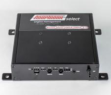
Adaptronic eSel010 ECU pictured in its manufacturer installation guide, page 1; reproduced with permission.
Rendered revisions
Open each version to inspect formatting, tables and photographs.
Revision 4: Adaptronic eSel010
Adaptronic eSel010 is a Select-series vehicle plug-in programmable engine-management ECU. The surviving manufacturer guide identifies the intended application as Nissan S14 Silvia / 200SX SR20DET and S13 CA18DET applications. Adaptronic eSel010 application and installation guide.
Identification and application
Confirm the case label and part number, original ECU and loom connector, engine, market and any vehicle-specific equipment against the guide before purchase or installation. Vehicle wiring can vary, and a shared plug shape does not establish pin compatibility.
Software and installation
The Select family uses Adaptronic WARI software, which is listed in Haltech’s legacy Adaptronic downloads archive. Use the matching eSel010 guide and application-specific basemap; the guide documents installation, configuration and pin references. A plug-in ECU still requires configuration and tuning for the actual engine and equipment.
Wiring and pinout
The manufacturer eSel010 guide contains the model and application-specific connector information. Positions and functions can change by application, and factory function and Adaptronic function are separate columns in the guide. The manufacturer connector table is transcribed below; verify the source and viewpoint before use.
Support and sources
Haltech states that Adaptronic operations ended in 2022. Refer to its Adaptronic notice and archived guides, and confirm current support and compatibility for used hardware. A verified product photograph for this exact part has not yet been added.
Transcribed from the Adaptronic eSel010 installation guide. Compare the application-specific descriptions, and configure the internal jumper for the relevant ignition output. The source gives numbering from the loom side, looking into the ECU. In the vehicle-connector tables, “NC” is the source's designation for no factory loom connection; a blank Adaptronic entry means no connection to the Adaptronic ECU. A dash in the table reproduces a blank source field.
Aux Output 1 cannot be used due to the fourth ignition output
3
To Igniter for Cylinder 3 (CA18)
Ignition output 2
—
4
Idle Control Valve (SR20)
Aux Output 2
—
5
Auto Transmission
—
—
6
Air conditioner output (CA18)
—
—
7
Tacho out
Aux Output 8
—
8
NC
Digital Input 5
Available as external input
9
Aircon relay (SR20)
Aux Output 7
—
10
Ground
Power Ground
—
11
Igniter for Cyl 3 (SR20), Cyl 4 (CA18)
Ignition output 2 or 3
Internal jumper to select input
12
To Igniter for Cylinder 4 (SR20)
Ignition output 3
—
13
NC
—
—
14
Auto Transmission
—
—
15
Auto Transmission
—
—
16
ECCS relay
—
When pin 45 has 12V, this pin is pulled low to activate the ECCS main relay
17
NC
Aux Temp input
—
18
Fuel pump relay
Aux Output 5
—
19
Cooling fan relay 1
Aux Output 6
Internally connected to aux output 6 to run at full speed.
20
Ground
Power Ground
—
21
Data link connector
Digital Input 6
Available as external input
22
Data link connector
Digital Input 7
Available as external input
23
Knock sensor signal
Knock input
—
24
NC
Digital Input 8
—
25
Boost control
Aux Output 3
—
26
Air Flow Meter
—
—
27
Air Flow Meter
—
—
28
Engine Coolant Temperature
ECT signal input
—
29
O2/EGO sensor signal
O2/EGO signal input
0-1V sensor input. Max 3V
30
Sensor ground
Sensor Ground
—
31
Data link connector
CAS 3 input
Available as flex fuel input
32
Malfunction indicator lamp
—
—
33
Cooling fan relay 2
Aux Output 6
—
34
Power steering load input
Digital Input 2
—
35
Factory MAP sensor signal
MAP signal input
On some cars there is already a MAP sensor on the engine, called 'Boost Pressure Sensor'. We recommend using the 4 bar internal MAP sensor on the ECU
36
NC
Air temp input
Not connected from factory, but can be used as an air temp input
37
NC
External 0-5V input
—
38
TPS signal
TPS signal input
—
39
NC
SVSS 1
Front left wheel speed, also available as flex fuel input
40
NC
SVSS 2
Front right wheel speed input
41
180 deg Cam Angle Sensor Signal
CAS 2 input
Variable-width pulses each period, for cylinder and TDC identification
42
1 deg Cam Angle Sensor Signal
CAS 1 input
1 degree pulses for calculating ignition timing
43
Starter
—
—
44
Neutral switch
Digital Input 1
—
45
Ignition switch
+12V Ignition
When this switches to 12V, the ECCS main relay is activated (see pin 16)
46
Aircon request input
Digital Input 3
—
47
Data link connector
—
—
48
+5V out
+5V output
+5V power supply for sensors
49
Power from ECCS relay
—
—
50
Ground
Power Ground
—
51
180 deg Cam Angle Sensor Signal
CAS 2 input
Connected to pin 41
52
1 deg Cam Angle Sensor Signal
CAS 1 input
Connected to pin 42
53
Speedometer
MVSS1
Gearbox speed sensor, or rear left wheel speed input
54
Rear window defogger load input
Digital Input 4
—
55
NC
MVSS2
Available as rear right wheel speed input or flex fuel input
56
Auto Transmission
—
—
57
NC
—
—
58
Constant Power
—
—
59
Power from ECCS relay
—
—
60
Ground
Power Ground
—
Manufacturer photograph
Adaptronic eSel010 ECU pictured in its manufacturer installation guide, page 1; reproduced with permission.Revision 4: Adaptronic eSel010
Adaptronic eSel010 is a Select-series vehicle plug-in programmable engine-management ECU. The surviving manufacturer guide identifies the intended application as Nissan S14 Silvia / 200SX SR20DET and S13 CA18DET applications. Adaptronic eSel010 application and installation guide.
Identification and application
Confirm the case label and part number, original ECU and loom connector, engine, market and any vehicle-specific equipment against the guide before purchase or installation. Vehicle wiring can vary, and a shared plug shape does not establish pin compatibility.
Software and installation
The Select family uses Adaptronic WARI software, which is listed in Haltech’s legacy Adaptronic downloads archive. Use the matching eSel010 guide and application-specific basemap; the guide documents installation, configuration and pin references. A plug-in ECU still requires configuration and tuning for the actual engine and equipment.
Wiring and pinout
The manufacturer eSel010 guide contains the model and application-specific connector information. Positions and functions can change by application, and factory function and Adaptronic function are separate columns in the guide. The manufacturer connector table is transcribed below; verify the source and viewpoint before use.
Support and sources
Haltech states that Adaptronic operations ended in 2022. Refer to its Adaptronic notice and archived guides, and confirm current support and compatibility for used hardware. A verified product photograph for this exact part has not yet been added.
Transcribed from the Adaptronic eSel010 installation guide. Compare the application-specific descriptions, and configure the internal jumper for the relevant ignition output. The source gives numbering from the loom side, looking into the ECU. In the vehicle-connector tables, “NC” is the source's designation for no factory loom connection; a blank Adaptronic entry means no connection to the Adaptronic ECU. A dash in the table reproduces a blank source field.