Removed text is struck through; added text is highlighted.
The Adaptronic eMod010 is an application-specific plug-in programmable engine-management ECU. Haltech's surviving Adaptronic downloads archive identifies the application as Mazda RX-7 FC Series 5. The part number identifies a family of applications, not an unconditional guarantee of vehicle compatibility. Haltech Adaptronic downloads archive.
Application and installation
Identify the vehicle, engine, connector and wiring variation before installation. Plug-in installation can still require additional sensor and actuator wiring, and tuning to suit the specific engine. The manufacturer archive provides the Adaptronic plug-in ECU startup guide and EUGENE tuning software.
Model-specific pinout
In the eMod010 section of the manufacturer download archive, find: RX7_S5_Pinout.zip. Open the matching vehicle-specific diagram; connector or pin functions cannot safely be inferred from a different eMod or a different application. The archive also lists the following basemap resource: eMod010_RX7S5_Basemap.ecu.
RX-7 Series 5 FC Turbo connector assignments
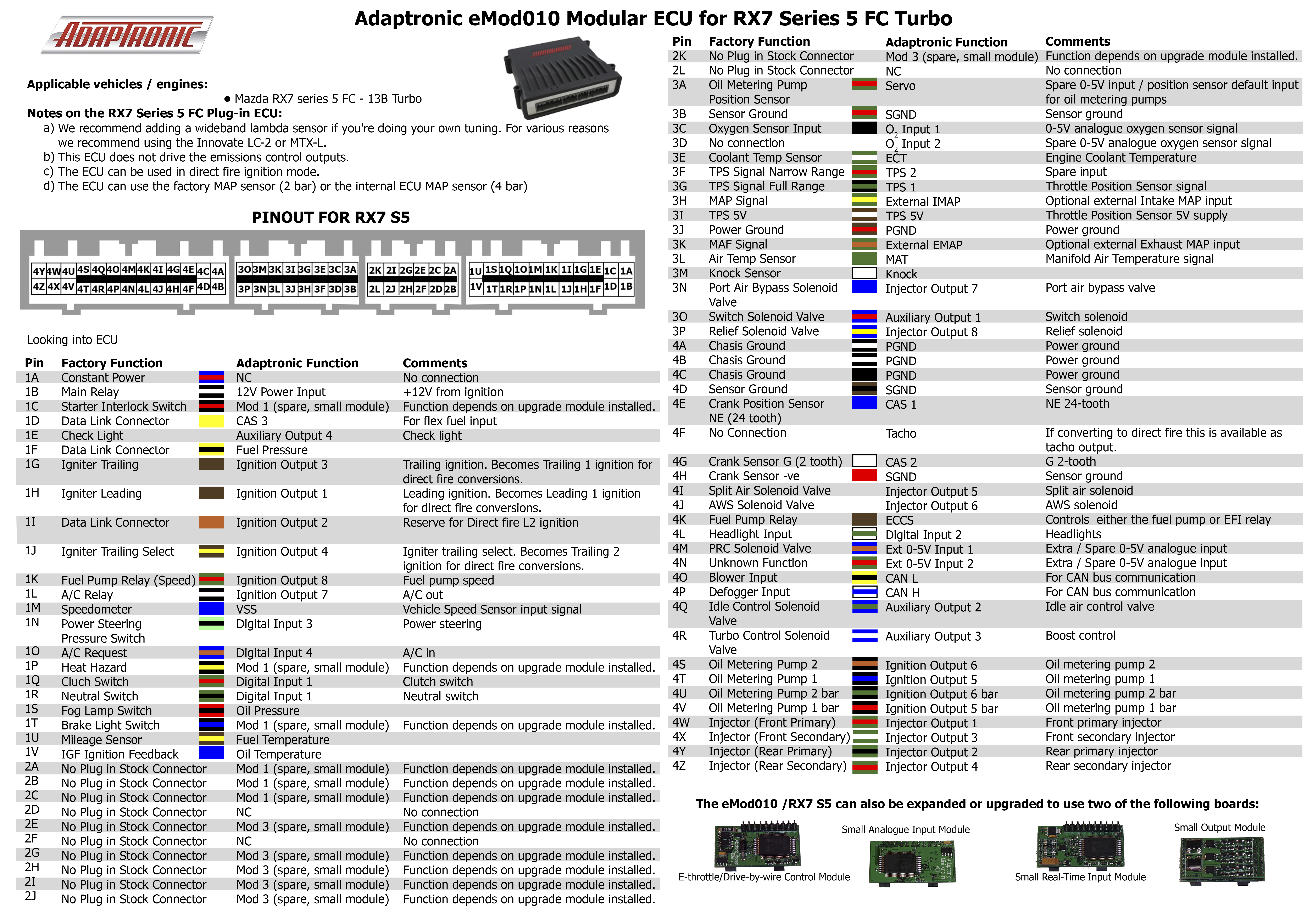
From Adaptronic’s eMod010 RX7 S5 pinout archive, for the RX-7 FC Series 5 13B turbo. Connector drawing is viewed looking into the ECU; these are Adaptronic functions, not necessarily factory functions. Module positions depend on the installed board. NC is no connection per source. The manufacturer lists both 1Q and 1R as digital input 1; verify against the actual ECU and manufacturer rather than assuming they are separate channels. “Bar” is retained from the manufacturer output names. Confirm connector, vehicle configuration and source diagram before wiring.
PositionAdaptronic function / notes1ANC1B12 V power input from ignition1CModule 1; function depends on installed module1DCAS 3 (flex-fuel input)1EAuxiliary output 4 (check light)1FFuel pressure1GIgnition output 3 (trailing / trailing 1 direct fire)1HIgnition output 1 (leading / leading 1 direct fire)1IIgnition output 2 (direct-fire L2)1JIgnition output 4 (trailing select / trailing 2 direct fire)1KIgnition output 8 (fuel pump speed)1LIgnition output 7 (A/C output)1MVSS1NDigital input 3 (power steering)1ODigital input 4 (A/C request)1PModule 1; function depends on installed module1QDigital input 1 (clutch switch)1RDigital input 1 (neutral switch)1SOil pressure1TModule 1; function depends on installed module1UFuel temperature1VOil temperature2AModule 1; function depends on installed module2BModule 1; function depends on installed module2CModule 1; function depends on installed module2DNC2EModule 3; function depends on installed module2FNC2GModule 3; function depends on installed module2HModule 3; function depends on installed module2IModule 3; function depends on installed module2JModule 3; function depends on installed module2KModule 3; function depends on installed module2LNC3AServo / oil-metering pump position input (0–5 V)3BSensor ground3CO2 input 1 (0–5 V)3DO2 input 2 (spare 0–5 V)3EEngine coolant temperature3FTPS 2 (spare input)3GTPS 13HExternal intake MAP3ITPS 5 V3JPower ground3KExternal exhaust MAP3LManifold air temperature3MKnock3NInjector output 7 (port air bypass)3OAuxiliary output 1 (switch solenoid)3PInjector output 8 (relief solenoid)4APower ground4BPower ground4CPower ground4DSensor ground4ECAS 1 (NE 24-tooth)4FTacho (available for direct-fire conversion)4GCAS 2 (G 2-tooth)4HSensor ground4IInjector output 5 (split-air solenoid)4JInjector output 6 (AWS solenoid)4KECCS (fuel pump or EFI relay)4LDigital input 2 (headlights)4MExternal 0–5 V input 14NExternal 0–5 V input 24OCAN L4PCAN H4QAuxiliary output 2 (idle air)4RAuxiliary output 3 (boost control)4SIgnition output 6 (oil-metering pump 2)4TIgnition output 5 (oil-metering pump 1)4UIgnition output 6 bar (oil-metering pump 2 bar)4VIgnition output 5 bar (oil-metering pump 1 bar)4WInjector output 1 (front primary)4XInjector output 3 (front secondary)4YInjector output 2 (rear primary)4ZInjector output 4 (rear secondary)
Documentation limits
Complete channel counts and additional variants have not been independently verified for this exact model. Haltech's Adaptronic notice records the end of Adaptronic operations in 2022; use the archived documentation and confirm present support before purchasing a used ECU.
Manufacturer connector diagram and ECU photograph
Adaptronic eMod010 model-specific ECU photograph and connector diagram, looking into the ECU. Source: Adaptronic / Haltech archived pinout ZIP; reproduced with permission. Consult the original installation notes and confirm the vehicle and hardware variant.
Connector pinoutA structured pinout with redrawn pin-index diagrams for all four connectors (76 positions) is on Adaptronic eMod010 connector pinout. Diagram redrawn by Tuning Wiki from the Adaptronic RX7_S5_Pinout archive (manufacturer documentation).
Rendered revisions
Open each version to inspect formatting, tables and photographs.
Revision 3: Adaptronic eMod010
The Adaptronic eMod010 is an application-specific plug-in programmable engine-management ECU. Haltech's surviving Adaptronic downloads archive identifies the application as Mazda RX-7 FC Series 5. The part number identifies a family of applications, not an unconditional guarantee of vehicle compatibility. Haltech Adaptronic downloads archive.
Application and installation
Identify the vehicle, engine, connector and wiring variation before installation. Plug-in installation can still require additional sensor and actuator wiring, and tuning to suit the specific engine. The manufacturer archive provides the Adaptronic plug-in ECU startup guide and EUGENE tuning software.
Model-specific pinout
In the eMod010 section of the manufacturer download archive, find: RX7_S5_Pinout.zip. Open the matching vehicle-specific diagram; connector or pin functions cannot safely be inferred from a different eMod or a different application. The archive also lists the following basemap resource: eMod010_RX7S5_Basemap.ecu.
RX-7 Series 5 FC Turbo connector assignments
From Adaptronic’s eMod010 RX7 S5 pinout archive, for the RX-7 FC Series 5 13B turbo. Connector drawing is viewed looking into the ECU; these are Adaptronic functions, not necessarily factory functions. Module positions depend on the installed board. NC is no connection per source. The manufacturer lists both 1Q and 1R as digital input 1; verify against the actual ECU and manufacturer rather than assuming they are separate channels. “Bar” is retained from the manufacturer output names. Confirm connector, vehicle configuration and source diagram before wiring.
Position
Adaptronic function / notes
1A
NC
1B
12 V power input from ignition
1C
Module 1; function depends on installed module
1D
CAS 3 (flex-fuel input)
1E
Auxiliary output 4 (check light)
1F
Fuel pressure
1G
Ignition output 3 (trailing / trailing 1 direct fire)
1H
Ignition output 1 (leading / leading 1 direct fire)
1I
Ignition output 2 (direct-fire L2)
1J
Ignition output 4 (trailing select / trailing 2 direct fire)
1K
Ignition output 8 (fuel pump speed)
1L
Ignition output 7 (A/C output)
1M
VSS
1N
Digital input 3 (power steering)
1O
Digital input 4 (A/C request)
1P
Module 1; function depends on installed module
1Q
Digital input 1 (clutch switch)
1R
Digital input 1 (neutral switch)
1S
Oil pressure
1T
Module 1; function depends on installed module
1U
Fuel temperature
1V
Oil temperature
2A
Module 1; function depends on installed module
2B
Module 1; function depends on installed module
2C
Module 1; function depends on installed module
2D
NC
2E
Module 3; function depends on installed module
2F
NC
2G
Module 3; function depends on installed module
2H
Module 3; function depends on installed module
2I
Module 3; function depends on installed module
2J
Module 3; function depends on installed module
2K
Module 3; function depends on installed module
2L
NC
3A
Servo / oil-metering pump position input (0–5 V)
3B
Sensor ground
3C
O2 input 1 (0–5 V)
3D
O2 input 2 (spare 0–5 V)
3E
Engine coolant temperature
3F
TPS 2 (spare input)
3G
TPS 1
3H
External intake MAP
3I
TPS 5 V
3J
Power ground
3K
External exhaust MAP
3L
Manifold air temperature
3M
Knock
3N
Injector output 7 (port air bypass)
3O
Auxiliary output 1 (switch solenoid)
3P
Injector output 8 (relief solenoid)
4A
Power ground
4B
Power ground
4C
Power ground
4D
Sensor ground
4E
CAS 1 (NE 24-tooth)
4F
Tacho (available for direct-fire conversion)
4G
CAS 2 (G 2-tooth)
4H
Sensor ground
4I
Injector output 5 (split-air solenoid)
4J
Injector output 6 (AWS solenoid)
4K
ECCS (fuel pump or EFI relay)
4L
Digital input 2 (headlights)
4M
External 0–5 V input 1
4N
External 0–5 V input 2
4O
CAN L
4P
CAN H
4Q
Auxiliary output 2 (idle air)
4R
Auxiliary output 3 (boost control)
4S
Ignition output 6 (oil-metering pump 2)
4T
Ignition output 5 (oil-metering pump 1)
4U
Ignition output 6 bar (oil-metering pump 2 bar)
4V
Ignition output 5 bar (oil-metering pump 1 bar)
4W
Injector output 1 (front primary)
4X
Injector output 3 (front secondary)
4Y
Injector output 2 (rear primary)
4Z
Injector output 4 (rear secondary)
Documentation limits
Complete channel counts and additional variants have not been independently verified for this exact model. Haltech's Adaptronic notice records the end of Adaptronic operations in 2022; use the archived documentation and confirm present support before purchasing a used ECU.
Manufacturer connector diagram and ECU photograph
Adaptronic eMod010 model-specific ECU photograph and connector diagram, looking into the ECU. Source: Adaptronic / Haltech archived pinout ZIP; reproduced with permission. Consult the original installation notes and confirm the vehicle and hardware variant.Revision 4: Adaptronic eMod010
The Adaptronic eMod010 is an application-specific plug-in programmable engine-management ECU. Haltech's surviving Adaptronic downloads archive identifies the application as Mazda RX-7 FC Series 5. The part number identifies a family of applications, not an unconditional guarantee of vehicle compatibility. Haltech Adaptronic downloads archive.
Application and installation
Identify the vehicle, engine, connector and wiring variation before installation. Plug-in installation can still require additional sensor and actuator wiring, and tuning to suit the specific engine. The manufacturer archive provides the Adaptronic plug-in ECU startup guide and EUGENE tuning software.
Model-specific pinout
In the eMod010 section of the manufacturer download archive, find: RX7_S5_Pinout.zip. Open the matching vehicle-specific diagram; connector or pin functions cannot safely be inferred from a different eMod or a different application. The archive also lists the following basemap resource: eMod010_RX7S5_Basemap.ecu.
RX-7 Series 5 FC Turbo connector assignments
From Adaptronic’s eMod010 RX7 S5 pinout archive, for the RX-7 FC Series 5 13B turbo. Connector drawing is viewed looking into the ECU; these are Adaptronic functions, not necessarily factory functions. Module positions depend on the installed board. NC is no connection per source. The manufacturer lists both 1Q and 1R as digital input 1; verify against the actual ECU and manufacturer rather than assuming they are separate channels. “Bar” is retained from the manufacturer output names. Confirm connector, vehicle configuration and source diagram before wiring.
Position
Adaptronic function / notes
1A
NC
1B
12 V power input from ignition
1C
Module 1; function depends on installed module
1D
CAS 3 (flex-fuel input)
1E
Auxiliary output 4 (check light)
1F
Fuel pressure
1G
Ignition output 3 (trailing / trailing 1 direct fire)
1H
Ignition output 1 (leading / leading 1 direct fire)
1I
Ignition output 2 (direct-fire L2)
1J
Ignition output 4 (trailing select / trailing 2 direct fire)
1K
Ignition output 8 (fuel pump speed)
1L
Ignition output 7 (A/C output)
1M
VSS
1N
Digital input 3 (power steering)
1O
Digital input 4 (A/C request)
1P
Module 1; function depends on installed module
1Q
Digital input 1 (clutch switch)
1R
Digital input 1 (neutral switch)
1S
Oil pressure
1T
Module 1; function depends on installed module
1U
Fuel temperature
1V
Oil temperature
2A
Module 1; function depends on installed module
2B
Module 1; function depends on installed module
2C
Module 1; function depends on installed module
2D
NC
2E
Module 3; function depends on installed module
2F
NC
2G
Module 3; function depends on installed module
2H
Module 3; function depends on installed module
2I
Module 3; function depends on installed module
2J
Module 3; function depends on installed module
2K
Module 3; function depends on installed module
2L
NC
3A
Servo / oil-metering pump position input (0–5 V)
3B
Sensor ground
3C
O2 input 1 (0–5 V)
3D
O2 input 2 (spare 0–5 V)
3E
Engine coolant temperature
3F
TPS 2 (spare input)
3G
TPS 1
3H
External intake MAP
3I
TPS 5 V
3J
Power ground
3K
External exhaust MAP
3L
Manifold air temperature
3M
Knock
3N
Injector output 7 (port air bypass)
3O
Auxiliary output 1 (switch solenoid)
3P
Injector output 8 (relief solenoid)
4A
Power ground
4B
Power ground
4C
Power ground
4D
Sensor ground
4E
CAS 1 (NE 24-tooth)
4F
Tacho (available for direct-fire conversion)
4G
CAS 2 (G 2-tooth)
4H
Sensor ground
4I
Injector output 5 (split-air solenoid)
4J
Injector output 6 (AWS solenoid)
4K
ECCS (fuel pump or EFI relay)
4L
Digital input 2 (headlights)
4M
External 0–5 V input 1
4N
External 0–5 V input 2
4O
CAN L
4P
CAN H
4Q
Auxiliary output 2 (idle air)
4R
Auxiliary output 3 (boost control)
4S
Ignition output 6 (oil-metering pump 2)
4T
Ignition output 5 (oil-metering pump 1)
4U
Ignition output 6 bar (oil-metering pump 2 bar)
4V
Ignition output 5 bar (oil-metering pump 1 bar)
4W
Injector output 1 (front primary)
4X
Injector output 3 (front secondary)
4Y
Injector output 2 (rear primary)
4Z
Injector output 4 (rear secondary)
Documentation limits
Complete channel counts and additional variants have not been independently verified for this exact model. Haltech's Adaptronic notice records the end of Adaptronic operations in 2022; use the archived documentation and confirm present support before purchasing a used ECU.
Manufacturer connector diagram and ECU photograph
Adaptronic eMod010 model-specific ECU photograph and connector diagram, looking into the ECU. Source: Adaptronic / Haltech archived pinout ZIP; reproduced with permission. Consult the original installation notes and confirm the vehicle and hardware variant.
Connector pinout
A structured pinout with redrawn pin-index diagrams for all four connectors (76 positions) is on Adaptronic eMod010 connector pinout. Diagram redrawn by Tuning Wiki from the Adaptronic RX7_S5_Pinout archive (manufacturer documentation).