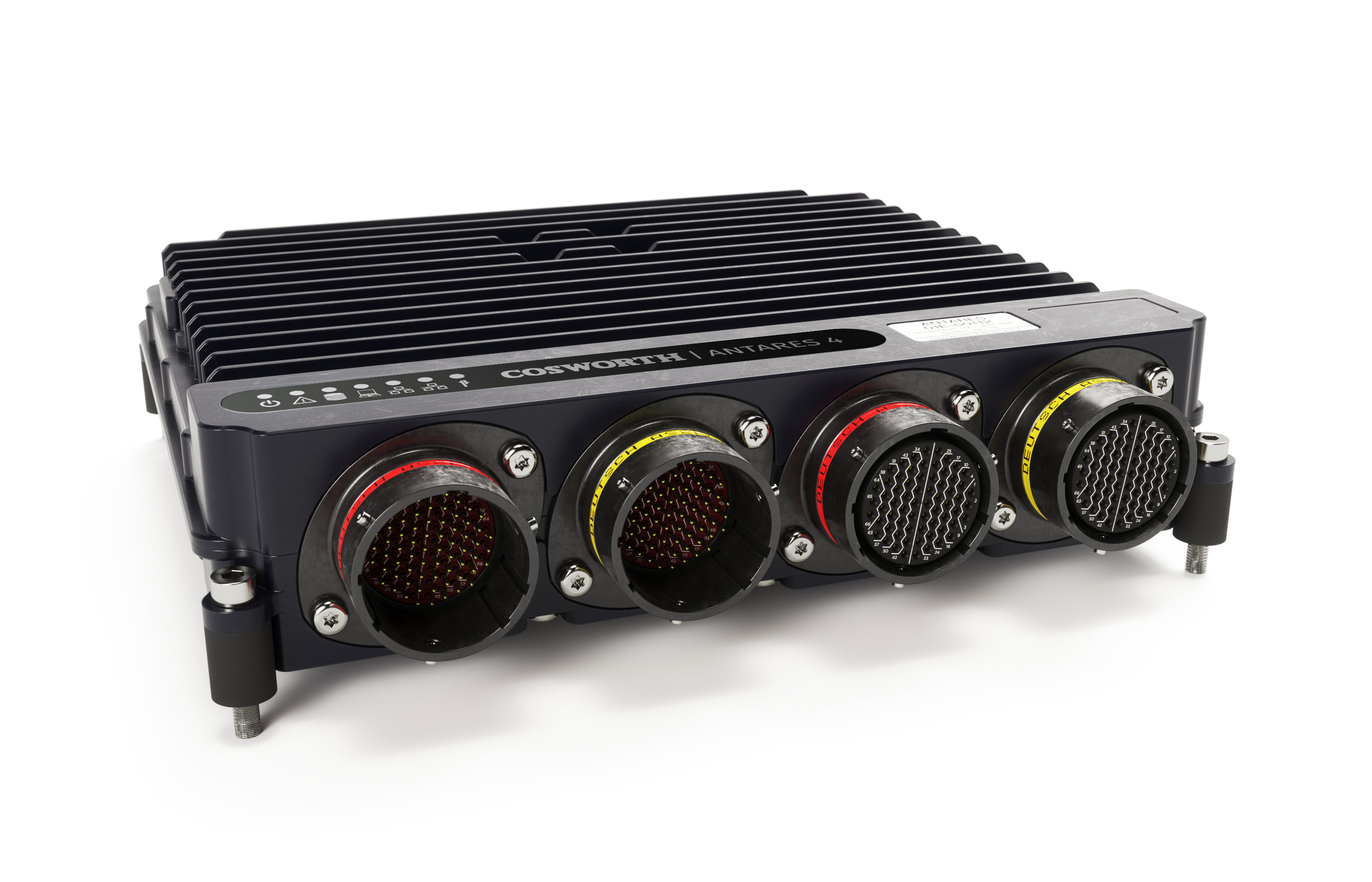
The Antares 4 is a Cosworth Antares family ECU and vehicle controller. Cosworth describes it as a lower-cost entry in its Antares range while retaining data-logging and powertrain-control functions. Cosworth product information.
Manufacturer product specification
Cosworth's Antares 4 product page describes optimisation for 4-cylinder GDI or 8-cylinder port injection; it lists 3 CAN ports, 4 GB logging, two onboard lambda inputs, two knock inputs and three H-bridge pairs. Maximum counts include alternative functions, so they are not necessarily simultaneously available. Confirm hardware and enabled strategy against the current build.
A separate family comparison leaflet gives different cylinder/driver figures from the product page; these should not be reconciled without revision-specific confirmation. Use the exact build sheet and software from Cosworth for the installation.
Identification and control
Confirm the exact ordered configuration and obtain the matching connector and calibration documents from Cosworth. Antares family feature headlines do not establish that every feature is enabled on this particular unit. Document the exact part number, serial, software build, calibration, championship configuration and any security or software option before assessing compatibility.
Connectors and wiring
Review the model-specific Cosworth document and request the current build sheet where necessary. Connector and driver assignments may be model-, build- and configuration-dependent. Sensor supplies, peak driver currents, earths and high-voltage injector circuits must be matched to the official document.
Software and support
Cosworth's Pectel application notes cover model-specific strategies; confirm toolchain and access level with the supplier. See the Cosworth Pectel and Antares family for related controllers.
Connector schedules in Cosworth’s Antares 4 sheet
The tables list all 66 numbered positions for each of four connectors from Cosworth’s Antares 4 product sheet, cover version 0.3. Signal names and connector part numbers follow that sheet; “not labelled in source” denotes an empty signal cell and must not be read as a confirmed unused pin. Where the sheet shows two pins for one signal, both are listed individually. Consult the source for the paired-pin notation, wiring, current limits, optional functions, grounds and orientation.
Document identification discrepancy: the cover and ordering table identify Antares 4 and product 01E-501154, but the final page identifies document 29E-501156-P, revision 1.0; 01E-501156 is identified elsewhere by Cosworth as Antares 6. The cover and final page also show different version numbers. Confirm the document and pin assignments for the exact unit directly with Cosworth before wiring.
C1 — AS218-35PN-943B; mating AS618-35SN
| Pin | Signal in source |
|---|---|
| 1 | INJLS2/PWM4 |
| 2 | INJHS2/PWM3 |
| 3 | IGN4/PWM46 |
| 4 | INJLS1/PWM2 |
| 5 | INJHS1/PWM1 |
| 6 | BATT- |
| 7 | IGN4/PWM46 |
| 8 | IGN3/PWM45 |
| 9 | IGN2/PWM44 |
| 10 | INJHS4/PWM7 |
| 11 | BATT- |
| 12 | BATT- |
| 13 | Serial2_TX_CTRL |
| 14 | IGN3/PWM45 |
| 15 | IGN2/PWM44 |
| 16 | IGN1/PWM43 |
| 17 | INJLS4/PWM8 |
| 18 | BATT+ |
| 19 | BATT- |
| 20 | BATT- |
| 21 | Serial2_RX_CTRL |
| 22 | SerialDBG_RX_LOG |
| 23 | IGN1/PWM43 |
| 24 | Serial1_TX_LOG |
| 25 | INJLS11/PWM19 |
| 26 | BATT+ |
| 27 | BATT+ |
| 28 | BATT- |
| 29 | BATT+ |
| 30 | SerialDBG_TX_LOG |
| 31 | DOUT2/PWM52 |
| 32 | Serial1_RX_LOG |
| 33 | ETHTRX-1 |
| 34 | INJLS12/PWM20 |
| 35 | BATT+ |
| 36 | BATT+ |
| 37 | BATT- |
| 38 | BATT+ |
| 39 | DOUT1/PWM51 |
| 40 | DOUT4/PWM54 |
| 41 | ETHTRX+1 |
| 42 | ETHTX-1 |
| 43 | INJHS3/PWM5 |
| 44 | BATT+ |
| 45 | HBB2/PWM36 |
| 46 | BATT- |
| 47 | CANH_CTRL-LOG |
| 48 | DOUT3/PWM53 |
| 49 | HBA1/PWM33 |
| 50 | ETHTX+1 |
| 51 | INJLS3/PWM6 |
| 52 | HBB2/PWM36 |
| 53 | HBA2/PWM35 |
| 54 | BATT- |
| 55 | CANL_CTRL-LOG |
| 56 | HBB1/PWM34 |
| 57 | HBA1/PWM33 |
| 58 | INJLS9/PWM17 |
| 59 | INJLS10/PWM18 |
| 60 | HBA2/PWM35 |
| 61 | BATT- |
| 62 | INJLS14/PWM22 |
| 63 | HBB1/PWM34 |
| 64 | INJLS15/PWM23 |
| 65 | INJLS16/PWM24 |
| 66 | INJLS13/PWM21 |
C2 — AS218-35PA-943B; mating AS618-35SA
| Pin | Signal in source |
|---|---|
| 1 | ECATTX+ |
| 2 | ECATRX- |
| 3 | ETH1000+4 |
| 4 | EXTPSU11 |
| 5 | EXTPSU12 |
| 6 | ECATTX- |
| 7 | ECATRX+ |
| 8 | ETH1000-4 |
| 9 | ETH1000-3 |
| 10 | EXTPSU13 |
| 11 | EXTPSU14 |
| 12 | CANL_LOG |
| 13 | CANH_LOG |
| 14 | N/C |
| 15 | ETH1000+3 |
| 16 | ETH1000+2 |
| 17 | EXTPSU4 |
| 18 | EXTPSU2 |
| 19 | DOUT8/PWM58 |
| 20 | DOUT6/PWM56 |
| 21 | DOUT7/PWM57 |
| 22 | N/C |
| 23 | ETH1000-2 |
| 24 | ETH1000+1 |
| 25 | EXTPSU3 |
| 26 | EXTPSU1 |
| 27 | AIN2 |
| 28 | AIN1 |
| 29 | AIN4 |
| 30 | DOUT5/PWM55 |
| 31 | Not labelled in source |
| 32 | ETH1000-1 |
| 33 | DIN1/AIN |
| 34 | TCNEG2 |
| 35 | LamTrim2 |
| 36 | LamTrim1 |
| 37 | AIN5 |
| 38 | AIN6 |
| 39 | AIN3 |
| 40 | Not labelled in source |
| 41 | DIN2/AIN |
| 42 | LAMVS1 |
| 43 | TCPOS2 |
| 44 | TCPOS1 |
| 45 | DIN6/AIN |
| 46 | N / C |
| 47 | KNOCK1 |
| 48 | N / C |
| 49 | LAMIP1 |
| 50 | KNOCK2 |
| 51 | TCNEG1 |
| 52 | DIN7/AIN |
| 53 | DIN4/AIN |
| 54 | Not labelled in source |
| 55 | DIN5/AIN |
| 56 | DIN3/AIN |
| 57 | LAMVS2 |
| 58 | DIN8/AIN |
| 59 | Not labelled in source |
| 60 | PROT-GND2 |
| 61 | N / C |
| 62 | CRANK1 |
| 63 | LAMIP2 |
| 64 | PROT-GND1 |
| 65 | PROT-GND2 |
| 66 | CAM |
C3 — AS218-35SN-943B; mating AS618-35PN
| Pin | Signal in source |
|---|---|
| 1 | Not labelled in source |
| 2 | EXTPSU19 |
| 3 | ETH2_TX- /FM1 |
| 4 | AIN HS1/CPM1 |
| 5 | Not labelled in source |
| 6 | EXTPSU21 |
| 7 | ETH2_TX+ /FP1 |
| 8 | ETH2_RX- /FM2 |
| 9 | ETH2_RX+ /FP2 |
| 10 | AIN HS3/CPM3 |
| 11 | N/C |
| 12 | Not labelled in source |
| 13 | N/C |
| 14 | N/C |
| 15 | CANL_CTRL |
| 16 | CANH_CTRL |
| 17 | AIN HS4/CPM4 |
| 18 | AIN HS2/CPM2 |
| 19 | N/C |
| 20 | Not labelled in source |
| 21 | PT1000 1 / AIN |
| 22 | AIN18 |
| 23 | AIN13 |
| 24 | AIN14 |
| 25 | N/C |
| 26 | Not labelled in source |
| 27 | Not labelled in source |
| 28 | Not labelled in source |
| 29 | Not labelled in source |
| 30 | N/C |
| 31 | AIN17 |
| 32 | AIN11 |
| 33 | AIN12 |
| 34 | N/C |
| 35 | N/C |
| 36 | Not labelled in source |
| 37 | Not labelled in source |
| 38 | Not labelled in source |
| 39 | AIN16 |
| 40 | DIN HS2/AIN |
| 41 | AIN9 |
| 42 | AIN10 |
| 43 | N/C |
| 44 | PROT-GND3 |
| 45 | AIN8 |
| 46 | AIN19 |
| 47 | AIN15 |
| 48 | DIN HS1/AIN |
| 49 | EXTPSU18 |
| 50 | EXTPSU16 |
| 51 | PROT-GND3 |
| 52 | PROT-GND4 |
| 53 | AIN7 |
| 54 | N/C |
| 55 | N/C |
| 56 | ScopeOut2 |
| 57 | ScopeOut1 |
| 58 | PROT-GND4 |
| 59 | EXTPSU5 |
| 60 | EXTPSU6 |
| 61 | EXTPSU7 |
| 62 | EXTPSU15 |
| 63 | EXTPSU17 |
| 64 | EXTPSU8 |
| 65 | EXTPSU9 |
| 66 | EXTPSU10 |
C4 — AS218-35SA-943B; mating AS618-35PA
| Pin | Signal in source |
|---|---|
| 1 | N/C |
| 2 | IGN5/PWM47 |
| 3 | IGN6/PWM48 |
| 4 | N/C |
| 5 | N/C |
| 6 | IGN5/PWM47 |
| 7 | IGN6/PWM48 |
| 8 | IGN7/PWM49 |
| 9 | IGN8/PWM50 |
| 10 | N/C |
| 11 | BATT- |
| 12 | BATT- |
| 13 | BATT- |
| 14 | IGN7/PWM49 |
| 15 | IGN8/PWM50 |
| 16 | N/C |
| 17 | N/C |
| 18 | Not labelled in source |
| 19 | BATT- |
| 20 | LIN1 |
| 21 | Not labelled in source |
| 22 | Not labelled in source |
| 23 | N/C |
| 24 | Not labelled in source |
| 25 | N/C |
| 26 | BATT- |
| 27 | BATT- |
| 28 | LIN2 |
| 29 | Not labelled in source |
| 30 | Not labelled in source |
| 31 | N/C |
| 32 | N/C |
| 33 | EXTPSU20 |
| 34 | INJLS19 / PWM27 |
| 35 | BATT+ |
| 36 | N/C |
| 37 | Not labelled in source |
| 38 | Not labelled in source |
| 39 | N/C |
| 40 | N/C |
| 41 | N/C |
| 42 | EXTPSU22 |
| 43 | INJLS20 / PWM28 |
| 44 | BATT+ |
| 45 | BATT+ |
| 46 | HBB3/PWM38 |
| 47 | N/C |
| 48 | Not labelled in source |
| 49 | PROT-GND5 |
| 50 | PROT-GND5 |
| 51 | N/C |
| 52 | BATT+ |
| 53 | HBB3/PWM38 |
| 54 | HBA3/PWM37 |
| 55 | Not labelled in source |
| 56 | PROT-GND6 |
| 57 | PROT-GND6 |
| 58 | N/C |
| 59 | INJLS17 / PWM25 |
| 60 | HBA3/PWM37 |
| 61 | Not labelled in source |
| 62 | N/C |
| 63 | N/C |
| 64 | INJLS18 / PWM26 |
| 65 | N/C |
| 66 | N/C |