Removed text is struck through; added text is highlighted.
Original FAST self-tuning fuel-injection system, distinguished from fuel-and-ignition EZ-EFI 2.0.
Identification and functions
The original EZ-EFI is a self-tuning fuel system. FAST explicitly describes it as fuel-only when contrasting it with EZ-EFI 2.0; a conventional distributor can retain its own timing control. Systems include throttle-body and multipoint variants. Use the manufacturer's EZ-EFI update and support information and the appropriate original-version manual; a compatible ECU replacement is not a universal pinout for every 2.0 product.
Wiring and support
Identify ECU part number, software version, harness and engine before connecting inputs or outputs. Exact pin functions depend on the specific unit, harness and optional drivers. FAST's software and documentation index separates its families. A missing pinout is not evidence that a related system uses the same connector.
See the FAST manufacturer index. Sources reviewed 17 November 2026.
Original EZ-EFI ECU connector
The FAST original EZ-EFI instructions, part FAST4-152, revised 19 April 2011, include wiring schematic 30227, revision A, on PDF page 33. The manufacturer labels 36 ECU positions as follows. CAN positions 2 and 3 are labeled but no harness wire is drawn for them in this schematic. Follow the original schematic and identify the harness before wiring; this schedule is distinct from EZ-EFI 2.0.
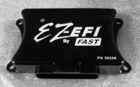
Original EZ-EFI ECU; manufacturer image from the FAST installation instructions, PDF page 2. Reproduced with permission.
Rendered revisions
Open each version to inspect formatting, tables and photographs.
Revision 3: FAST EZ-EFI
Original FAST self-tuning fuel-injection system, distinguished from fuel-and-ignition EZ-EFI 2.0.
Identification and functions
The original EZ-EFI is a self-tuning fuel system. FAST explicitly describes it as fuel-only when contrasting it with EZ-EFI 2.0; a conventional distributor can retain its own timing control. Systems include throttle-body and multipoint variants. Use the manufacturer's EZ-EFI update and support information and the appropriate original-version manual; a compatible ECU replacement is not a universal pinout for every 2.0 product.
Wiring and support
Identify ECU part number, software version, harness and engine before connecting inputs or outputs. Exact pin functions depend on the specific unit, harness and optional drivers. FAST's software and documentation index separates its families. A missing pinout is not evidence that a related system uses the same connector.
The FAST original EZ-EFI instructions, part FAST4-152, revised 19 April 2011, include wiring schematic 30227, revision A, on PDF page 33. The manufacturer labels 36 ECU positions as follows. CAN positions 2 and 3 are labeled but no harness wire is drawn for them in this schematic. Follow the original schematic and identify the harness before wiring; this schedule is distinct from EZ-EFI 2.0.
ECU pin
Signal
Harness wire colour
1
Injector A
Black
2
CAN L
Not shown
3
CAN H
Not shown
4
12 V switched
Pink
5
MAP
White/violet
6
CTS
White
7
ATS
White/pink
8
TPS
White/red
9
O2 Ip / P+
Red
10
Power ground
Black
11
N/A
—
12
RPM input
Yellow
13
O2 Vs/Ip / S+
Yellow
14
O2 Rcal / P−
Green
15
IAC A-LO
Blue
16
IAC A-HI
Red
17
IAC B-HI
Yellow
18
Injector D
Green
19
Injector B
Brown
20
Fan
Blue
21
PC TXD
Red
22
PC RXD
Black
23
Analog ground
Black/pink
24
O2 H− / H−
White
25
PC RTN
White
26
Fuel pump
Light green
27
A/C input
Gray
28
Power ground
Black
29
O2 Vs / R+
Black
30
N/A
—
31
Battery
Red
32
5 V reference
Red/white
33
N/A
—
34
N/A
—
35
IAC B-LO
Black
36
Injector C
Yellow
Original EZ-EFI ECU; manufacturer image from the FAST installation instructions, PDF page 2. Reproduced with permission.Revision 3: FAST EZ-EFI
Original FAST self-tuning fuel-injection system, distinguished from fuel-and-ignition EZ-EFI 2.0.
Identification and functions
The original EZ-EFI is a self-tuning fuel system. FAST explicitly describes it as fuel-only when contrasting it with EZ-EFI 2.0; a conventional distributor can retain its own timing control. Systems include throttle-body and multipoint variants. Use the manufacturer's EZ-EFI update and support information and the appropriate original-version manual; a compatible ECU replacement is not a universal pinout for every 2.0 product.
Wiring and support
Identify ECU part number, software version, harness and engine before connecting inputs or outputs. Exact pin functions depend on the specific unit, harness and optional drivers. FAST's software and documentation index separates its families. A missing pinout is not evidence that a related system uses the same connector.
The FAST original EZ-EFI instructions, part FAST4-152, revised 19 April 2011, include wiring schematic 30227, revision A, on PDF page 33. The manufacturer labels 36 ECU positions as follows. CAN positions 2 and 3 are labeled but no harness wire is drawn for them in this schematic. Follow the original schematic and identify the harness before wiring; this schedule is distinct from EZ-EFI 2.0.
ECU pin
Signal
Harness wire colour
1
Injector A
Black
2
CAN L
Not shown
3
CAN H
Not shown
4
12 V switched
Pink
5
MAP
White/violet
6
CTS
White
7
ATS
White/pink
8
TPS
White/red
9
O2 Ip / P+
Red
10
Power ground
Black
11
N/A
—
12
RPM input
Yellow
13
O2 Vs/Ip / S+
Yellow
14
O2 Rcal / P−
Green
15
IAC A-LO
Blue
16
IAC A-HI
Red
17
IAC B-HI
Yellow
18
Injector D
Green
19
Injector B
Brown
20
Fan
Blue
21
PC TXD
Red
22
PC RXD
Black
23
Analog ground
Black/pink
24
O2 H− / H−
White
25
PC RTN
White
26
Fuel pump
Light green
27
A/C input
Gray
28
Power ground
Black
29
O2 Vs / R+
Black
30
N/A
—
31
Battery
Red
32
5 V reference
Red/white
33
N/A
—
34
N/A
—
35
IAC B-LO
Black
36
Injector C
Yellow
Original EZ-EFI ECU; manufacturer image from the FAST installation instructions, PDF page 2. Reproduced with permission.