Tuning Wiki

This is a historical revision. Read the current page or return to its history.

Page organisation in this revision
Page type
Reference hub
Subject
Engine ECU
Parent
Syvecs Standalone ECUs
Applies to
No ECU-specific applicability
Tool groups
None
Manufacturers
None

Changes from revision 4 to revision 4

Removed text is struck through; added text is highlighted.

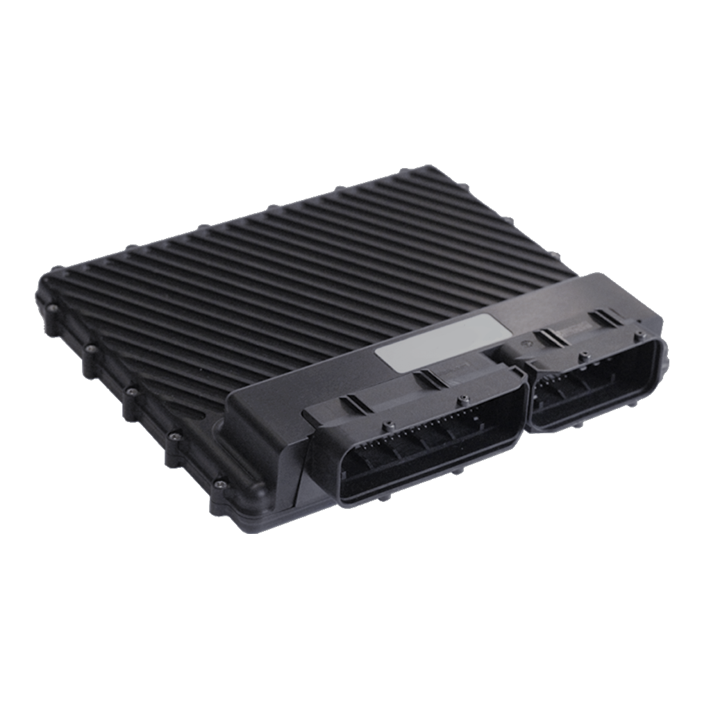
Syvecs S12 standalone ECU shown as a family illustration. This vehicle-specific kit and its adapter or wiring are not pictured and may differ. Image: Syvecs, reproduced with permission.

Model and vehicle application

Syvecs lists this vehicle-specific standalone or plug-in ECU kit as Lamborghini Gallardo LP520 S12, with product code S12-LAM520. The product page and its stated vehicle, model and transmission details define this particular application; confirm market, model year, engine, ECU connector and transmission against Syvecs before ordering.

This entry describes the dedicated vehicle kit. It is distinct from the generic wire-in ECU: a plug-in kit can use application-specific adaptor wiring, a carrier, additional modules and an application calibration. The listed hardware or supported equipment can vary by revision.

Wiring and pinout

Syvecs Lamborghini Gallardo LP520 S12 installation and wiring document. Follow the connector orientation, application-specific tables, installation notes and hardware revision in this document. Do not transfer assignments from another vehicle merely because the underlying ECU family is similar. The link was checked to return a PDF.

For other variants and manual revisions consult the manufacturer's vehicle-specific manual index. Available spare inputs and outputs can be used only within their electrical limits and with a matching calibration.

Calibration and service

Use the correct Syvecs software, firmware and base calibration for the exact vehicle and installed hardware. The Syvecs software portal and firmware archive provide manufacturer support. A base map is a starting point and needs checking against the actual engine, injectors, sensors and modifications.

Sources

Syvecs Lamborghini Gallardo LP520 S12 product listing and applicationManufacturer kit installation and pinout manualSyvecs plug-in kit support index

Manufacturer S12 connector schedule

From pages 9–11 of the Syvecs Gallardo LP520 installation guide, version 1.2. The chart contains the 121 S12 ECU positions and kit notes; it is not a complete vehicle connector schedule. A dash reproduces a blank in the manufacturer table. Verify the kit and loom revision and connector orientation.

S12 pinPin functionSCAL nameKit connection1PWRGNDEcu GroundGround2IGN1Ignition (20A Open Collector)Ignition13IGN2Ignition (20A Open Collector)Ignition24IGN3Ignition (20A Open Collector)Ignition35IGN4Ignition (20A Open Collector)Ignition46IN25—SPARE 0‐5v Input7KNOCK4Knock Sensor 2Knock Sensor 28KNOCKGND—Knock Grounds9THERMO2 +—SPARE EGT10IN21Thermistor InputSpare Thermistor Input11IN185V Analogue InputSpare 0‐5v Input12IN14Configurable Analogue InputSpare Programmable Input13IN11Configurable Analogue InputExhaust Cam114IN7Configurable Analogue InputSpare Programmable Input15IN4Configurable Analogue InputMap Sensor16IN1Configurable Analogue InputEngine Oil Pressure17LAMI 1—Lam1 ion18CAN LO 2—Spare CanBus19RS232 TX—RS232 Transmit20LAN RX‐—Orange/White Cat521FUEL 7Fuel Injector (10A Open Collector)Tacho Output22FUEL 3Fuel Injector (10A Open Collector)Injector 323VBAT—12v Supply24PWRGND—Spare Ground25IN265V Analogue InputSpare 0‐5v Input265V OUT5V OUT5v Ref27KNK1KNOCK1Knock Sensor 128THERMO 1 ‐THERMO 1 ‐Spare EGT29IN22Thermistor InputSpare Thermistor Input30IN195V InputPedal Position 231IN15Configurable Analogue InputCam vvt1 in32IN12Configurable Analogue InputSpare Programmable Input33IN08Configurable Analogue InputA/C Switch34ANGNDSENSOR GROUNDSensor Ground35IN02Configurable Analogue InputAir Charge Temp36LAMV 1—Lam1V37CAN HI 3—Spare CanBus38RS232 RX—Rs232 Receive39LAN RX+—White/Orange Cat540FUEL8—VVT1 Intake41FUEL4—Injector 442VBAT—12v Supply43PWRGND—Ground44IN275VSpare 0‐5v Input455V OUT—5v Ref46KNOCK2—Knock Sensor247THERMO1+—Spare EGT48IN23Thermistor InputEngine Coolant Temp49IN205VPedal Position 150IN16Configurable Analogue InputSpare Programmable Input51ANGND—Sensor Grounds52IN09Configurable Analogue InputExhaust Cam 253IN05Configurable Analogue InputCrank Sensor54ANGND—Sensor Ground55LAMV2—Lam2 V56CAN LO 3—Spare CanBus57COMGND—Comms Ground58CAN HI 1—Connected Can Bus59LAN TX‐—Green/White Cat560FUEL5—VVT Exhaust 161FUEL1—Injector 162HBRIDGE5—Spare Half Bridge Output63IN285VSpare 0‐5v Input6410VOUT—Configurable sensor voltage output65KNOCK 3—Knock 366THEMO 02 ‐—Spare EGT67IN24Thermistor InputOil Temp68ANGND—Sensor Ground69IN175VSpare 0‐5v Input70IN13—VVT2 Intake71IN10Configurable Analogue InputSport Switch72IN6Configurable Analogue InputBrake Pressure73IN3Configurable Analogue InputSpare Programmable Input74LAMI 2—Lam2 I75LamGND—Lambda Sensor Grounds76CAN HI 02—Spare Can Bus77CAN LO 1—Connected Can bus78LAN TX+—White/Green Cat579FUEL6—Injector 580FUEL2—Injector 281H BRIDGE 6—Spare Half bridge82H BRIDGE 1—Spare Half Bridge83PWM4—Fuel Pump Relays84PWM8—Rad Fans85FUEL12—Injector 886FUEL16—Injector 687FUEL20—VVT Ex 288FUEL24—VVT Intake 289VBAT—12v Supply90H BRIDGE 2—Spare Half Bridge91PWM3—Throttle Relay92PWM7—Main Relay93FUEL11—Injector 794FUEL15—Lambda Heaters95FUEL19—Spare Output96FUEL23—Spare Output97PWRGND—Ground98H BRIDGE 3—Spare Half Bridge99PWM2—Intake manifold Flap ‐ Ideal for Boost solenoid100PWM6—Oil Pressure Gauge (Pin Write Enable on GFA)101FUEL10—Oil Temp gauge ( Pin Crank waveform on GFA)102FUEL14—Injector 10103FUEL18—Spare Output104FUEL22—Spare Output105PWRGND—Ground106HBRIDGE4—Spare Half Bridge Output107PWM1—Spare Output108PWM5—Spare Output109FUEL9—Spare Output110FUEL13—Injector 9111FUEL17—Spare Output112FUEL21—Spare Output113PWRGND—Ground114IGN5—Ignition 5115IGN6—Ignition 6116IGN7—Ignition 7117IGN8—Ignition 8118IGN9—Ignition 9119IGN10—Ignition 10120IGN11—Ignition 11121IGN12—Ignition 12

Newer kit external 12-way DTM: documented positions

The manual calls this a 12-way connector but lists only the following ten numbered positions. Positions 11 and 12 remain unverified. It separately lists an older lettered 10-way connector; do not treat these as the same revision.

PinFunction1AN25 — spare 0–5 V input2AN26 — spare 0–5 V input3AN27 — spare 0–5 V input4+5 V supply5Analogue sensor ground6AN28 — spare 0–5 V input7H-bridge 1 — spare output8H-bridge 2 — spare output9H-bridge 3 — spare output10H-bridge 4 — spare output

Older kit external 10-way GT connector

The same manufacturer guide, page 7, lists this lettered connector separately for older kits.
PinFunctionAIN25 — spare 0–5 V inputBIN26 — spare 0–5 V inputCIN27 — spare 0–5 V inputD+5 V supplyEAnalogue sensor groundFIN28 — spare 0–5 V inputGH-bridge 1 — spare outputHH-bridge 2 — spare outputJH-bridge 3 — spare outputKH-bridge 4 — spare output

Rendered revisions

Open each version to inspect formatting, tables and photographs.

Revision 4: Syvecs Lamborghini Gallardo LP520 S12 Plug-in ECU
Syvecs S12 standalone ECU
Syvecs S12 standalone ECU shown as a family illustration. This vehicle-specific kit and its adapter or wiring are not pictured and may differ. Image: Syvecs, reproduced with permission.

Model and vehicle application

Syvecs lists this vehicle-specific standalone or plug-in ECU kit as Lamborghini Gallardo LP520 S12, with product code S12-LAM520. The product page and its stated vehicle, model and transmission details define this particular application; confirm market, model year, engine, ECU connector and transmission against Syvecs before ordering.

This entry describes the dedicated vehicle kit. It is distinct from the generic wire-in ECU: a plug-in kit can use application-specific adaptor wiring, a carrier, additional modules and an application calibration. The listed hardware or supported equipment can vary by revision.

Wiring and pinout

Syvecs Lamborghini Gallardo LP520 S12 installation and wiring document. Follow the connector orientation, application-specific tables, installation notes and hardware revision in this document. Do not transfer assignments from another vehicle merely because the underlying ECU family is similar. The link was checked to return a PDF.

For other variants and manual revisions consult the manufacturer's vehicle-specific manual index. Available spare inputs and outputs can be used only within their electrical limits and with a matching calibration.

Calibration and service

Use the correct Syvecs software, firmware and base calibration for the exact vehicle and installed hardware. The Syvecs software portal and firmware archive provide manufacturer support. A base map is a starting point and needs checking against the actual engine, injectors, sensors and modifications.

Sources

Manufacturer S12 connector schedule

From pages 9–11 of the Syvecs Gallardo LP520 installation guide, version 1.2. The chart contains the 121 S12 ECU positions and kit notes; it is not a complete vehicle connector schedule. A dash reproduces a blank in the manufacturer table. Verify the kit and loom revision and connector orientation.

S12 pinPin functionSCAL nameKit connection
1PWRGNDEcu GroundGround
2IGN1Ignition (20A Open Collector)Ignition1
3IGN2Ignition (20A Open Collector)Ignition2
4IGN3Ignition (20A Open Collector)Ignition3
5IGN4Ignition (20A Open Collector)Ignition4
6IN25—SPARE 0‐5v Input
7KNOCK4Knock Sensor 2Knock Sensor 2
8KNOCKGND—Knock Grounds
9THERMO2 +—SPARE EGT
10IN21Thermistor InputSpare Thermistor Input
11IN185V Analogue InputSpare 0‐5v Input
12IN14Configurable Analogue InputSpare Programmable Input
13IN11Configurable Analogue InputExhaust Cam1
14IN7Configurable Analogue InputSpare Programmable Input
15IN4Configurable Analogue InputMap Sensor
16IN1Configurable Analogue InputEngine Oil Pressure
17LAMI 1—Lam1 ion
18CAN LO 2—Spare CanBus
19RS232 TX—RS232 Transmit
20LAN RX‐—Orange/White Cat5
21FUEL 7Fuel Injector (10A Open Collector)Tacho Output
22FUEL 3Fuel Injector (10A Open Collector)Injector 3
23VBAT—12v Supply
24PWRGND—Spare Ground
25IN265V Analogue InputSpare 0‐5v Input
265V OUT5V OUT5v Ref
27KNK1KNOCK1Knock Sensor 1
28THERMO 1 ‐THERMO 1 ‐Spare EGT
29IN22Thermistor InputSpare Thermistor Input
30IN195V InputPedal Position 2
31IN15Configurable Analogue InputCam vvt1 in
32IN12Configurable Analogue InputSpare Programmable Input
33IN08Configurable Analogue InputA/C Switch
34ANGNDSENSOR GROUNDSensor Ground
35IN02Configurable Analogue InputAir Charge Temp
36LAMV 1—Lam1V
37CAN HI 3—Spare CanBus
38RS232 RX—Rs232 Receive
39LAN RX+—White/Orange Cat5
40FUEL8—VVT1 Intake
41FUEL4—Injector 4
42VBAT—12v Supply
43PWRGND—Ground
44IN275VSpare 0‐5v Input
455V OUT—5v Ref
46KNOCK2—Knock Sensor2
47THERMO1+—Spare EGT
48IN23Thermistor InputEngine Coolant Temp
49IN205VPedal Position 1
50IN16Configurable Analogue InputSpare Programmable Input
51ANGND—Sensor Grounds
52IN09Configurable Analogue InputExhaust Cam 2
53IN05Configurable Analogue InputCrank Sensor
54ANGND—Sensor Ground
55LAMV2—Lam2 V
56CAN LO 3—Spare CanBus
57COMGND—Comms Ground
58CAN HI 1—Connected Can Bus
59LAN TX‐—Green/White Cat5
60FUEL5—VVT Exhaust 1
61FUEL1—Injector 1
62HBRIDGE5—Spare Half Bridge Output
63IN285VSpare 0‐5v Input
6410VOUT—Configurable sensor voltage output
65KNOCK 3—Knock 3
66THEMO 02 ‐—Spare EGT
67IN24Thermistor InputOil Temp
68ANGND—Sensor Ground
69IN175VSpare 0‐5v Input
70IN13—VVT2 Intake
71IN10Configurable Analogue InputSport Switch
72IN6Configurable Analogue InputBrake Pressure
73IN3Configurable Analogue InputSpare Programmable Input
74LAMI 2—Lam2 I
75LamGND—Lambda Sensor Grounds
76CAN HI 02—Spare Can Bus
77CAN LO 1—Connected Can bus
78LAN TX+—White/Green Cat5
79FUEL6—Injector 5
80FUEL2—Injector 2
81H BRIDGE 6—Spare Half bridge
82H BRIDGE 1—Spare Half Bridge
83PWM4—Fuel Pump Relays
84PWM8—Rad Fans
85FUEL12—Injector 8
86FUEL16—Injector 6
87FUEL20—VVT Ex 2
88FUEL24—VVT Intake 2
89VBAT—12v Supply
90H BRIDGE 2—Spare Half Bridge
91PWM3—Throttle Relay
92PWM7—Main Relay
93FUEL11—Injector 7
94FUEL15—Lambda Heaters
95FUEL19—Spare Output
96FUEL23—Spare Output
97PWRGND—Ground
98H BRIDGE 3—Spare Half Bridge
99PWM2—Intake manifold Flap ‐ Ideal for Boost solenoid
100PWM6—Oil Pressure Gauge (Pin Write Enable on GFA)
101FUEL10—Oil Temp gauge ( Pin Crank waveform on GFA)
102FUEL14—Injector 10
103FUEL18—Spare Output
104FUEL22—Spare Output
105PWRGND—Ground
106HBRIDGE4—Spare Half Bridge Output
107PWM1—Spare Output
108PWM5—Spare Output
109FUEL9—Spare Output
110FUEL13—Injector 9
111FUEL17—Spare Output
112FUEL21—Spare Output
113PWRGND—Ground
114IGN5—Ignition 5
115IGN6—Ignition 6
116IGN7—Ignition 7
117IGN8—Ignition 8
118IGN9—Ignition 9
119IGN10—Ignition 10
120IGN11—Ignition 11
121IGN12—Ignition 12

Newer kit external 12-way DTM: documented positions

The manual calls this a 12-way connector but lists only the following ten numbered positions. Positions 11 and 12 remain unverified. It separately lists an older lettered 10-way connector; do not treat these as the same revision.

PinFunction
1AN25 — spare 0–5 V input
2AN26 — spare 0–5 V input
3AN27 — spare 0–5 V input
4+5 V supply
5Analogue sensor ground
6AN28 — spare 0–5 V input
7H-bridge 1 — spare output
8H-bridge 2 — spare output
9H-bridge 3 — spare output
10H-bridge 4 — spare output

Older kit external 10-way GT connector

The same manufacturer guide, page 7, lists this lettered connector separately for older kits.

PinFunction
AIN25 — spare 0–5 V input
BIN26 — spare 0–5 V input
CIN27 — spare 0–5 V input
D+5 V supply
EAnalogue sensor ground
FIN28 — spare 0–5 V input
GH-bridge 1 — spare output
HH-bridge 2 — spare output
JH-bridge 3 — spare output
KH-bridge 4 — spare output
Revision 4: Syvecs Lamborghini Gallardo LP520 S12 Plug-in ECU
Syvecs S12 standalone ECU
Syvecs S12 standalone ECU shown as a family illustration. This vehicle-specific kit and its adapter or wiring are not pictured and may differ. Image: Syvecs, reproduced with permission.

Model and vehicle application

Syvecs lists this vehicle-specific standalone or plug-in ECU kit as Lamborghini Gallardo LP520 S12, with product code S12-LAM520. The product page and its stated vehicle, model and transmission details define this particular application; confirm market, model year, engine, ECU connector and transmission against Syvecs before ordering.

This entry describes the dedicated vehicle kit. It is distinct from the generic wire-in ECU: a plug-in kit can use application-specific adaptor wiring, a carrier, additional modules and an application calibration. The listed hardware or supported equipment can vary by revision.

Wiring and pinout

Syvecs Lamborghini Gallardo LP520 S12 installation and wiring document. Follow the connector orientation, application-specific tables, installation notes and hardware revision in this document. Do not transfer assignments from another vehicle merely because the underlying ECU family is similar. The link was checked to return a PDF.

For other variants and manual revisions consult the manufacturer's vehicle-specific manual index. Available spare inputs and outputs can be used only within their electrical limits and with a matching calibration.

Calibration and service

Use the correct Syvecs software, firmware and base calibration for the exact vehicle and installed hardware. The Syvecs software portal and firmware archive provide manufacturer support. A base map is a starting point and needs checking against the actual engine, injectors, sensors and modifications.

Sources

Manufacturer S12 connector schedule

From pages 9–11 of the Syvecs Gallardo LP520 installation guide, version 1.2. The chart contains the 121 S12 ECU positions and kit notes; it is not a complete vehicle connector schedule. A dash reproduces a blank in the manufacturer table. Verify the kit and loom revision and connector orientation.

S12 pinPin functionSCAL nameKit connection
1PWRGNDEcu GroundGround
2IGN1Ignition (20A Open Collector)Ignition1
3IGN2Ignition (20A Open Collector)Ignition2
4IGN3Ignition (20A Open Collector)Ignition3
5IGN4Ignition (20A Open Collector)Ignition4
6IN25—SPARE 0‐5v Input
7KNOCK4Knock Sensor 2Knock Sensor 2
8KNOCKGND—Knock Grounds
9THERMO2 +—SPARE EGT
10IN21Thermistor InputSpare Thermistor Input
11IN185V Analogue InputSpare 0‐5v Input
12IN14Configurable Analogue InputSpare Programmable Input
13IN11Configurable Analogue InputExhaust Cam1
14IN7Configurable Analogue InputSpare Programmable Input
15IN4Configurable Analogue InputMap Sensor
16IN1Configurable Analogue InputEngine Oil Pressure
17LAMI 1—Lam1 ion
18CAN LO 2—Spare CanBus
19RS232 TX—RS232 Transmit
20LAN RX‐—Orange/White Cat5
21FUEL 7Fuel Injector (10A Open Collector)Tacho Output
22FUEL 3Fuel Injector (10A Open Collector)Injector 3
23VBAT—12v Supply
24PWRGND—Spare Ground
25IN265V Analogue InputSpare 0‐5v Input
265V OUT5V OUT5v Ref
27KNK1KNOCK1Knock Sensor 1
28THERMO 1 ‐THERMO 1 ‐Spare EGT
29IN22Thermistor InputSpare Thermistor Input
30IN195V InputPedal Position 2
31IN15Configurable Analogue InputCam vvt1 in
32IN12Configurable Analogue InputSpare Programmable Input
33IN08Configurable Analogue InputA/C Switch
34ANGNDSENSOR GROUNDSensor Ground
35IN02Configurable Analogue InputAir Charge Temp
36LAMV 1—Lam1V
37CAN HI 3—Spare CanBus
38RS232 RX—Rs232 Receive
39LAN RX+—White/Orange Cat5
40FUEL8—VVT1 Intake
41FUEL4—Injector 4
42VBAT—12v Supply
43PWRGND—Ground
44IN275VSpare 0‐5v Input
455V OUT—5v Ref
46KNOCK2—Knock Sensor2
47THERMO1+—Spare EGT
48IN23Thermistor InputEngine Coolant Temp
49IN205VPedal Position 1
50IN16Configurable Analogue InputSpare Programmable Input
51ANGND—Sensor Grounds
52IN09Configurable Analogue InputExhaust Cam 2
53IN05Configurable Analogue InputCrank Sensor
54ANGND—Sensor Ground
55LAMV2—Lam2 V
56CAN LO 3—Spare CanBus
57COMGND—Comms Ground
58CAN HI 1—Connected Can Bus
59LAN TX‐—Green/White Cat5
60FUEL5—VVT Exhaust 1
61FUEL1—Injector 1
62HBRIDGE5—Spare Half Bridge Output
63IN285VSpare 0‐5v Input
6410VOUT—Configurable sensor voltage output
65KNOCK 3—Knock 3
66THEMO 02 ‐—Spare EGT
67IN24Thermistor InputOil Temp
68ANGND—Sensor Ground
69IN175VSpare 0‐5v Input
70IN13—VVT2 Intake
71IN10Configurable Analogue InputSport Switch
72IN6Configurable Analogue InputBrake Pressure
73IN3Configurable Analogue InputSpare Programmable Input
74LAMI 2—Lam2 I
75LamGND—Lambda Sensor Grounds
76CAN HI 02—Spare Can Bus
77CAN LO 1—Connected Can bus
78LAN TX+—White/Green Cat5
79FUEL6—Injector 5
80FUEL2—Injector 2
81H BRIDGE 6—Spare Half bridge
82H BRIDGE 1—Spare Half Bridge
83PWM4—Fuel Pump Relays
84PWM8—Rad Fans
85FUEL12—Injector 8
86FUEL16—Injector 6
87FUEL20—VVT Ex 2
88FUEL24—VVT Intake 2
89VBAT—12v Supply
90H BRIDGE 2—Spare Half Bridge
91PWM3—Throttle Relay
92PWM7—Main Relay
93FUEL11—Injector 7
94FUEL15—Lambda Heaters
95FUEL19—Spare Output
96FUEL23—Spare Output
97PWRGND—Ground
98H BRIDGE 3—Spare Half Bridge
99PWM2—Intake manifold Flap ‐ Ideal for Boost solenoid
100PWM6—Oil Pressure Gauge (Pin Write Enable on GFA)
101FUEL10—Oil Temp gauge ( Pin Crank waveform on GFA)
102FUEL14—Injector 10
103FUEL18—Spare Output
104FUEL22—Spare Output
105PWRGND—Ground
106HBRIDGE4—Spare Half Bridge Output
107PWM1—Spare Output
108PWM5—Spare Output
109FUEL9—Spare Output
110FUEL13—Injector 9
111FUEL17—Spare Output
112FUEL21—Spare Output
113PWRGND—Ground
114IGN5—Ignition 5
115IGN6—Ignition 6
116IGN7—Ignition 7
117IGN8—Ignition 8
118IGN9—Ignition 9
119IGN10—Ignition 10
120IGN11—Ignition 11
121IGN12—Ignition 12

Newer kit external 12-way DTM: documented positions

The manual calls this a 12-way connector but lists only the following ten numbered positions. Positions 11 and 12 remain unverified. It separately lists an older lettered 10-way connector; do not treat these as the same revision.

PinFunction
1AN25 — spare 0–5 V input
2AN26 — spare 0–5 V input
3AN27 — spare 0–5 V input
4+5 V supply
5Analogue sensor ground
6AN28 — spare 0–5 V input
7H-bridge 1 — spare output
8H-bridge 2 — spare output
9H-bridge 3 — spare output
10H-bridge 4 — spare output

Older kit external 10-way GT connector

The same manufacturer guide, page 7, lists this lettered connector separately for older kits.

PinFunction
AIN25 — spare 0–5 V input
BIN26 — spare 0–5 V input
CIN27 — spare 0–5 V input
D+5 V supply
EAnalogue sensor ground
FIN28 — spare 0–5 V input
GH-bridge 1 — spare output
HH-bridge 2 — spare output
JH-bridge 3 — spare output
KH-bridge 4 — spare output