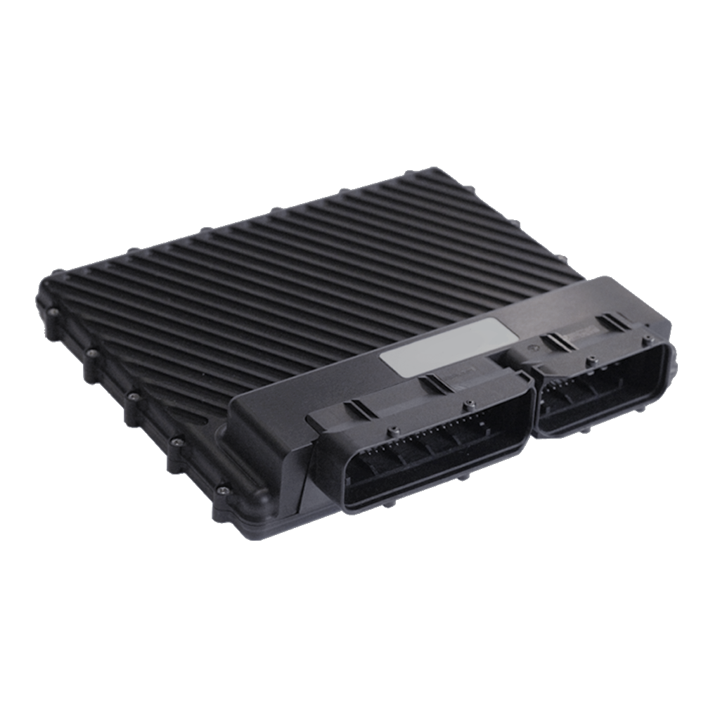
Model and vehicle application
Syvecs lists this vehicle-specific standalone or plug-in ECU kit as Audi R8 Gen2 2016 onward V10 S12, with product code S12-R8V1017. The product page and its stated vehicle, model and transmission details define this particular application; confirm market, model year, engine, ECU connector and transmission against Syvecs before ordering.
This entry describes the dedicated vehicle kit. It is distinct from the generic wire-in ECU: a plug-in kit can use application-specific adaptor wiring, a carrier, additional modules and an application calibration. The listed hardware or supported equipment can vary by revision.
Wiring and pinout
Syvecs Audi R8 Gen2 2016 onward V10 S12 installation and wiring document. Follow the connector orientation, application-specific tables, installation notes and hardware revision in this document. Do not transfer assignments from another vehicle merely because the underlying ECU family is similar. The link was checked to return a PDF.
For other variants and manual revisions consult the manufacturer's vehicle-specific manual index. Available spare inputs and outputs can be used only within their electrical limits and with a matching calibration.
Calibration and service
Use the correct Syvecs software, firmware and base calibration for the exact vehicle and installed hardware. The Syvecs software portal and firmware archive provide manufacturer support. A base map is a starting point and needs checking against the actual engine, injectors, sensors and modifications.
Sources
- Syvecs Audi R8 Gen2 2016 onward V10 S12 product listing and application
- Manufacturer kit installation and pinout manual
- Syvecs plug-in kit support index
Manufacturer S12 ECU connector schedule
From the Syvecs Huracán / R8 Gen2 kit installation guide, pages 9–11. This covers the 121 S12 ECU positions and manufacturer descriptions; the separate DI12 and factory vehicle connectors are not fully tabulated here. The chart's guide identifies the R8 Gen2 interface as 2017 onward, while the article's product range begins in 2016; confirm a 2016 vehicle and loom with Syvecs. A dash reproduces an empty entry in the chart.
| S12 pin | Syvecs function | Kit description |
|---|---|---|
| 1 | PWRGND | — |
| 2 | IGN01 | Ignition Coil Cyl 1 |
| 3 | IGN02 | Ignition Coil Cyl 2 |
| 4 | IGN03 | Ignition Coil Cyl 3 |
| 5 | IGN04 | Ignition Coil Cyl 4 |
| 6 | IN25 | Throttle Position 1a |
| 7 | KNOCK 4 | Knock + 4 |
| 8 | KNOCKGND | Knock Ground |
| 9 | THERMO 2 + _ | — |
| 10 | IN21 | MAF Air Temp 1 |
| 11 | IN18 | Pedal Position 1a |
| 12 | IN14 | Cam Position ‐ Exhaust 1 |
| 13 | IN11 | Cam Position ‐ Intake 1 |
| 14 | IN07 | Crank Position |
| 15 | IN04 | Starter Signal |
| 16 | IN01 | — |
| 17 | LAM 1 I | — |
| 18 | CAN 2 LO | — |
| 19 | RS232 TX | — |
| 20 | LAN RX‐ | Orange/White |
| 21 | FUEL07 | Sec Fuel Injector 1 |
| 22 | FUEL03 | Sec Fuel Injector 2 |
| 23 | VBAT | — |
| 24 | PWRGND | — |
| 25 | IN26 | Throttle Position 1b |
| 26 | 5V OUT | — |
| 27 | KNOCK 1 | Knock + 1 |
| 28 | THERMO 1 ‐ _ | — |
| 29 | IN22 | MAF Air Temp 2 |
| 30 | IN19 | Pedal Position 1b |
| 31 | IN15 | Cam Position ‐ Exhaust 2 |
| 32 | IN12 | Cam Position ‐ Intake 2 |
| 33 | IN08 | External Map Sensor |
| 34 | ANGND | Tank Pressure, Cam Sensor, |
| 35 | IN02 | — |
| 36 | LAM 1 V | Nernst Cell V |
| 37 | CAN 3 HI | — |
| 38 | RS232 RX | — |
| 39 | LAN RX+ | White/Orange |
| 40 | FUEL08 | Sec Fuel Injector 3 |
| 41 | FUEL04 | Sec Fuel Injector 4 |
| 42 | VBAT | — |
| 43 | PWRGND | — |
| 44 | IN27 | Throttle Position 2a |
| 45 | 5V OUT | — |
| 46 | KNOCK 2 | Knock + 2 |
| 47 | THERMO 1 + _ | — |
| 48 | IN23 | — |
| 49 | IN20 | Fuel Pressure ‐ Low Side1 |
| 50 | IN16 | Sec Air Pressure ( MAP 1) |
| 51 | ANGND | — |
| 52 | IN09 | Sec Air Pressure ( MAP 2) |
| 53 | IN05 | Brake Light Switch |
| 54 | ANGND | — |
| 55 | LAM 2 V | Neret Cell V |
| 56 | CAN 3 LO | — |
| 57 | RS232 GND | — |
| 58 | CAN 1 HI | — |
| 59 | LAN TX‐ | Green/White |
| 60 | FUEL05 | Sec Fuel Injector 5 |
| 61 | FUEL01 | Sec Fuel Injector 6 |
| 62 | HBRIDGE 6 | DBW 1b ‐ |
| 63 | IN28 | Throttle Position 2b |
| 64 | 10VOUT | — |
| 65 | KNOCK 3 | Knock + 3 |
| 66 | THERMO 2 ‐ _ | — |
| 67 | IN24 | Coolant Temp 1 |
| 68 | ANGND | — |
| 69 | IN17 | Fuel Pressure ‐ Low Side2 |
| 70 | IN13 | Fuel Pressure ‐ High Side 1 |
| 71 | IN10 | Fuel Pressure ‐ High Side2 |
| 72 | IN06 | — |
| 73 | IN03 | Oil Pressure SWiTCH |
| 74 | LAM 2 I | — |
| 75 | LAM GND | — |
| 76 | CAN 2 HI | — |
| 77 | CAN 1 LO | — |
| 78 | LAN TX+ | White/Green |
| 79 | FUEL06 | Sec Fuel Injector 7 |
| 80 | FUEL02 | Sec Fuel Injector 8 |
| 81 | HBRIDGE 5 | DBW 1 + |
| 82 | HBRIDGE 2 | DI Spill Valve 2 ‐ 12V |
| 83 | PWM4 | Lambda Heater B1 |
| 84 | PWM8 | Lambda Heater B2 |
| 85 | FUEL12 | Sec Fuel Injector 9 |
| 86 | FUEL16 | Sec Fuel Injector 10 |
| 87 | FUEL20 | Cam Adjuster B1 Intake |
| 88 | FUEL24 | Cam Adjuster B1 Exhaust |
| 89 | VBAT | — |
| 90 | HBRIDGE 1 | DI Spill Valve 1 ‐ 12v |
| 91 | PWM3 | Starter Relays |
| 92 | PWM7 | Brake Servo Relay |
| 93 | FUEL11 | Cam Adjuster B2 Intake |
| 94 | FUEL15 | Cam Adjuster B2 Exhaust |
| 95 | FUEL19 | DI12 Injector 1 |
| 96 | FUEL23 | DI12 Injector 2 |
| 97 | PWRGND | — |
| 98 | HBRIDGE 4 | DBW 2 ‐ |
| 99 | PWM2 | — |
| 100 | PWM6 | Boost control Sol |
| 101 | FUEL10 | DI12 Injector 3 |
| 102 | FUEL14 | DI12 Injector 4 |
| 103 | FUEL18 | DI12 Injector 5 |
| 104 | FUEL22 | DI12 Injector 6 |
| 105 | PWRGND | — |
| 106 | HBRIDGE 3 | DBW 2 + |
| 107 | PWM1 | FuelPump |
| 108 | PWM5 | Cooling Fans |
| 109 | FUEL09 | DI12 Injector 7 |
| 110 | FUEL13 | DI12 Injector 8 |
| 111 | FUEL17 | DI12 Injector 9 |
| 112 | FUEL21 | DI12 Injector 10 |
| 113 | PWRGND | — |
| 114 | IGN05 | Ignition Coil Cyl 5 |
| 115 | IGN06 | Ignition Coil Cyl 6 |
| 116 | IGN07 | Ignition Coil Cyl 7 |
| 117 | IGN08 | Ignition Coil Cyl 8 |
| 118 | IGN09 | Ignition Coil Cyl 9 |
| 119 | IGN10 | Ignition Coil Cyl 10 |
| 120 | IGN11 | DI Spill Valve 1 |
| 121 | IGN12 | DI Spill Valve 2 |