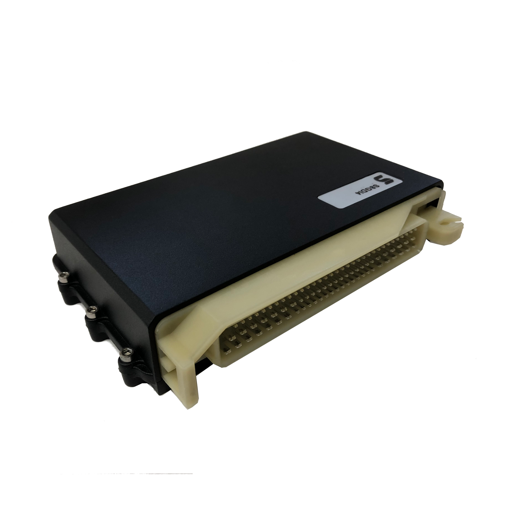
The Syvecs S-GDI4 (product code SYV-GDI4, also called SDI or GDi4 in Syvecs materials) is a standalone controller for gasoline direct injection, with an 88-position connector. Syvecs describes integrated control for four-cylinder GDI engines, Ethernet, RS232 and CAN communications, and support for auxiliary sensors and outputs. Confirm actual hardware and firmware against the manufacturer product listing.
Manufacturer 88-way pin schedule
The following is the manufacturer’s GDi4 Pinouts and Wiring Info, dated 3 February 2014, pages 2–3. These are hardware terminal labels and functions for the documented build; wiring and configuration for a particular vehicle kit can differ. In particular, the separately documented Fiesta ST kit describes a different function at terminal 45. Verify the kit, serial, board revision, connector view and calibration before applying a table.
| Pin | Manufacturer signal | Function |
|---|---|---|
| 1 | PWRGND | Power ground |
| 2 | IGN8 | Ignition output 8 |
| 3 | IGN7 | Ignition output 7 |
| 4 | IGN6 | Ignition output 6 |
| 5 | IGN5 | Ignition output 5 |
| 6 | FUEL10 | Fuel injector / PWM output 10 |
| 7 | KNK2 | Knock sensor 2 |
| 8 | AN16 | Configurable analogue / speed / frequency input 16 |
| 9 | AN14 | Configurable analogue / speed / frequency input 14 |
| 10 | AN12 | Configurable analogue / speed / frequency input 12 |
| 11 | AN10 | Configurable analogue / speed / frequency input 10 |
| 12 | H BRIDGE5 | H-bridge 5 |
| 13 | H BRIDGE6 | H-bridge 6 |
| 14 | AN7 | Configurable analogue / speed / frequency input 7 |
| 15 | AN5 | Configurable analogue / speed / frequency input 5 |
| 16 | AN3 | Configurable analogue / speed / frequency input 3 |
| 17 | AN1 | Configurable analogue / speed / frequency input 1 |
| 18 | LAM1V | NTK UEGO sensor 1 Nernst voltage |
| 19 | AN21 | Thermistor input 21 |
| 20 | FUEL15 | Fuel injector / PWM output 15 |
| 21 | RS232#1TX | RS232 transmit |
| 22 | FUEL7 | Fuel injector / PWM output 7 |
| 23 | FUEL5 | Spare output with flyback diode |
| 24 | GDI #4 + | GDI injector 4 positive |
| 25 | GDI #3 + | GDI injector 3 positive |
| 26 | GDI #2 + | GDI injector 2 positive |
| 27 | GDI #1 + | GDI injector 1 positive |
| 28 | PWRGND | ECU power ground |
| 29 | PWRGND | ECU power ground |
| 30 | FUEL14 | Fuel injector / PWM output 14 |
| 31 | FUEL13 | Fuel injector / PWM output 13 |
| 32 | FUEL12 / GDI PUMP − | Fuel output / GDI pump negative |
| 33 | FUEL11 | Fuel injector / PWM output 11 |
| 34 | FUEL9 | Fuel injector / PWM output 9 |
| 35 | KNK | Knock sensor 1 |
| 36 | AN15 | Configurable analogue / speed / frequency input 15 |
| 37 | AN13 | Configurable analogue / speed / frequency input 13 |
| 38 | AN11 | Configurable analogue / speed / frequency input 11 |
| 39 | AN9 | Configurable analogue / speed / frequency input 9 |
| 40 | EGT1− | K-type thermocouple 1 negative |
| 41 | AN8 | Configurable analogue / speed / frequency input 8 |
| 42 | AN6 | Configurable analogue / speed / frequency input 6 |
| 43 | AN4 | Configurable analogue / speed / frequency input 4 |
| 44 | AN2 | Configurable analogue / speed / frequency input 2 |
| 45 | LAM#2V | NTK UEGO sensor 2 Nernst voltage |
| 46 | AN22 | Thermistor input 22 |
| 47 | FUEL16 | Fuel injector / PWM output 16 |
| 48 | RS232#1RX | RS232 receive |
| 49 | FUEL8 | Fuel injector / PWM output 8 |
| 50 | FUEL6 | Spare output with flyback diode |
| 51 | GDI #4 − | GDI injector 4 negative |
| 52 | GDI #3 − | GDI injector 3 negative |
| 53 | GDI #2 − | GDI injector 2 negative |
| 54 | GDI #1 − | GDI injector 1 negative |
| 55 | PWRGND | ECU power ground |
| 56 | VBAT | ECU +12 V switched supply |
| 57 | VBAT | ECU +12 V switched supply |
| 58 | GDI PUMP + | GDI pump positive |
| 59 | H BRIDGE2 | H-bridge 2 |
| 60 | H BRIDGE3 | H-bridge 3 / DBW + |
| 61 | H BRIDGE4 | H-bridge 4 / DBW − |
| 62 | 10VOUT | Programmable low-current sensor output |
| 63 | 5VOUT2 | 5 V sensor supply 2 |
| 64 | 5VOUT1 | 5 V sensor supply 1 |
| 65 | KNKGND | Knock sensor ground |
| 66 | AN20 | 5 V analogue input 20 |
| 67 | ANGND2 | Sensor ground; source calls this ground 1 |
| 68 | AN19 | 5 V analogue input 19 |
| 69 | ANGND1 | Sensor ground; source calls this ground 2 |
| 70 | EGT1+ | K-type thermocouple 1 positive |
| 71 | AN18 | 5 V analogue input 18 |
| 72 | ANGND2 | Sensor ground 2 |
| 73 | AN17 | 5 V analogue input 17 |
| 74 | ANGND1 | Sensor ground 1 |
| 75 | LAM2I | NTK UEGO sensor 2 ion pump |
| 76 | LAMI | NTK UEGO sensor 1 ion pump |
| 77 | LAMGND | Lambda sensor signal ground |
| 78 | COMGND | RS232 communications ground |
| 79 | CAN2LO | CAN 2 low |
| 80 | CAN2HI | CAN 2 high |
| 81 | CAN1LO | CAN 1 low |
| 82 | CAN1HI | CAN 1 high |
| 83 | AN24 | Thermistor input 24 |
| 84 | AN23 | Thermistor input 23 |
| 85 | LANRX+ | Ethernet receive positive |
| 86 | LANRX− | Ethernet receive negative |
| 87 | LANTX+ | Ethernet transmit positive |
| 88 | LANTX− | Ethernet transmit negative |
In the 2014 source, pins 67 and 69 use ANGND2 and ANGND1 labels respectively, but their adjacent ground-number descriptions are reversed; both descriptions are retained and require manufacturer confirmation. The table refers to six H-bridge labels, whereas the product listing summarises four H-bridge outputs; treat the installed ECU’s revision and actual capabilities as unverified until confirmed. The manufacturer lists the injector-high-side connections for solenoid-type GDI injectors.
See the Fiesta ST180 plug-in page for its vehicle-specific wiring, and the Syvecs manufacturer index.