Tuning Wiki

This is a historical revision. Read the current page or return to its history.

Page organisation in this revision
Page type
Reference hub
Subject
Engine ECU
Parent
Adaptronic standalone ECUs
Applies to
No ECU-specific applicability
Tool groups
None
Manufacturers
None

Changes from revision 2 to revision 4

Removed text is struck through; added text is highlighted.

The Adaptronic eMod005 is an application-specific plug-in programmable engine-management ECU. Haltech's surviving Adaptronic downloads archive identifies the application as Nissan S13 180SX/Silvia redtop, S13 blacktop Type X, S14a 64-pin and S15. The part number identifies a family of applications, not an unconditional guarantee of vehicle compatibility. Haltech Adaptronic downloads archive.

Application and installation

Identify the vehicle, engine, connector and wiring variation before installation. Plug-in installation can still require additional sensor and actuator wiring, and tuning to suit the specific engine. The manufacturer archive provides the Adaptronic plug-in ECU startup guide and EUGENE tuning software.

Model-specific pinout

In the eMod005 section of the manufacturer download archive, find: separate S13 redtop, S13 Type X, S14a 64-pin and S15 pinout ZIP files. Open the matching vehicle-specific diagram; connector or pin functions cannot safely be inferred from a different eMod or a different application. The archive also lists the following basemap resource: separate S13, Type X, S14a and S15 basemaps.

Documentation limits

Complete channel counts and additional variants have not been independently verified for this exact model. Haltech's Adaptronic notice records the end of Adaptronic operations in 2022; use the archived documentation and confirm present support before purchasing a used ECU.

Manufacturer connector tables and photographs

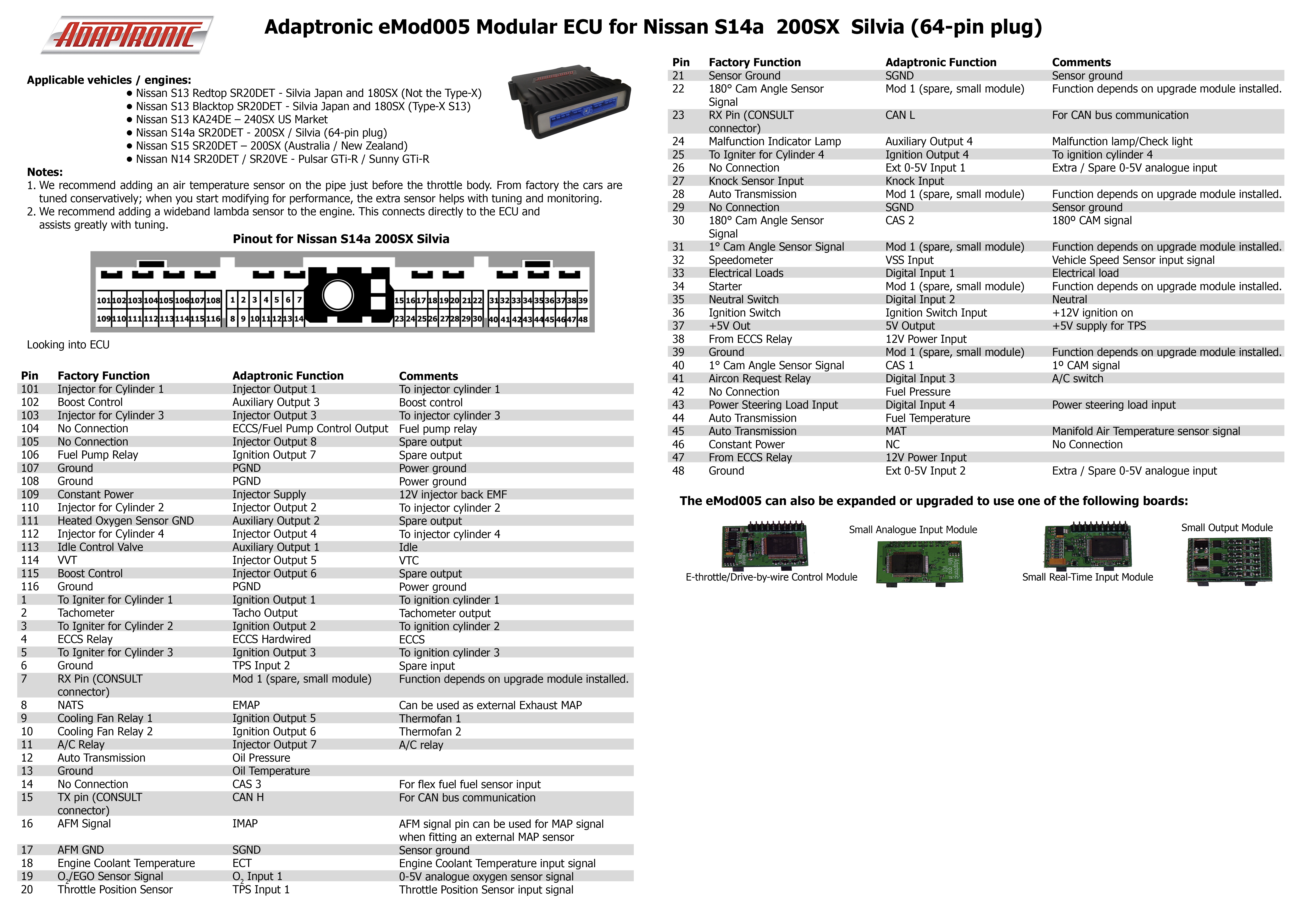
Illustrations: Adaptronic, preserved in the Haltech Adaptronic archive, reproduced with permission. Each manufacturer sheet includes a product photograph, connector orientation, factory function, Adaptronic function and manufacturer comments.

These are separate vehicle pinouts, viewed looking into the ECU; do not interchange application-specific factory functions.

S13 180SX/Silvia redtop SR20DET — open the full-size manufacturer connector diagram and table.
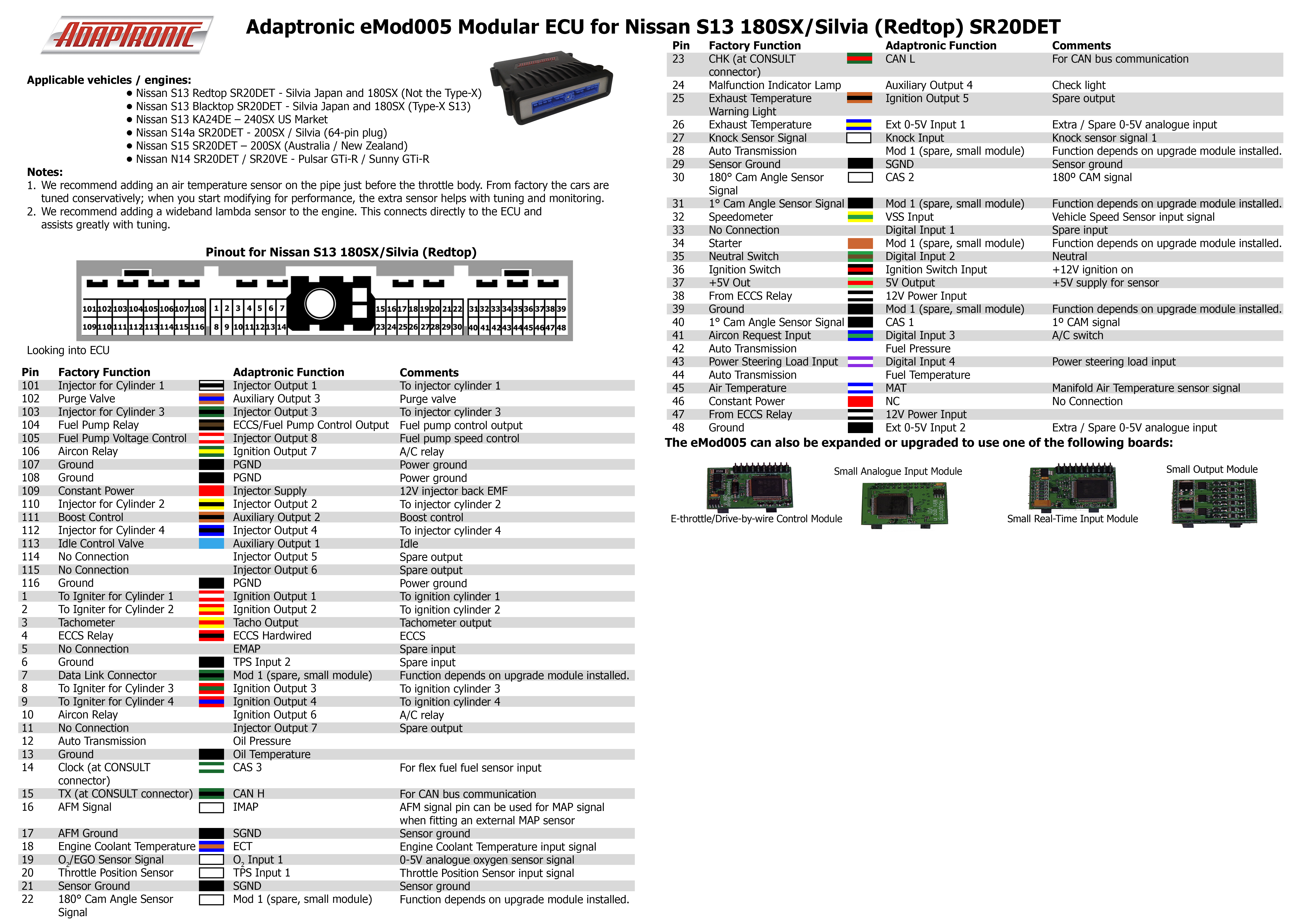
S13 180SX/Silvia blacktop Type X — open the full-size manufacturer connector diagram and table.

S14a 200SX/Silvia 64-pin — open the full-size manufacturer connector diagram and table.
S15 200SX/Silvia — connector table

The S15 table below transcribes the separate manufacturer S15 pinout ZIP. The sheet describes the S15 SR20DET 200SX Australia/New Zealand application. Factory and Adaptronic functions are separate columns; Mod 1 depends on the installed upgrade module. Refer to the original sheet for wire colours and manufacturer comments.The S15 table below transcribes the separate manufacturer S15 pinout ZIP. Its source image exceeds the wiki image size limit. The sheet describes the S15 SR20DET 200SX Australia/New Zealand application. Factory and Adaptronic functions are separate columns; Mod 1 depends on the installed upgrade module. Refer to the original sheet for wire colours and manufacturer comments.

PinFactory functionAdaptronic function101Injector cylinder 1Injector output 1102Boost controlAuxiliary output 3103Injector cylinder 3Injector output 3104No connectionECCS/fuel pump control output105Intake valve timing control solenoidInjector output 8106Fuel pump relayIgnition output 7107GroundPGND108GroundPGND109Constant powerInjector supply110Injector cylinder 2Injector output 2111Heated oxygen sensor groundAuxiliary output 2112Injector cylinder 4Injector output 4113Idle control valveAuxiliary output 1114VVTInjector output 5115Boost controlInjector output 6116GroundPGND1Igniter cylinder 1Ignition output 12TachometerTacho output3Igniter cylinder 2Ignition output 24ECCS relayECCS hardwired5Igniter cylinder 3Ignition output 36GroundTPS input 27CONSULT RX pinMod 18NATSEMAP9Cooling fan relay 1Ignition output 510Cooling fan relay 2Ignition output 611A/C relayInjector output 712Automatic transmissionOil pressure13GroundOil temperature14No connectionCAS 315CONSULT TX pinCAN H16AFM signalIMAP17AFM groundSGND18Engine coolant temperatureECT19Oxygen sensorO2 input 120Throttle position sensorTPS input 121Sensor groundSGND22Cam angle sensor 180°Mod 123CONSULT RX pinCAN L24Malfunction indicator lampAuxiliary output 425Igniter cylinder 4Ignition output 426No connectionExternal 0–5 V input 127Knock sensor inputKnock input28Automatic transmissionMod 129No connectionSGND30Cam angle sensor 180°CAS 231Cam angle sensor 1°Mod 132SpeedometerVSS input33Electrical loadsDigital input 134StarterMod 135Neutral switchDigital input 236Ignition switchIgnition switch input37+5 V output5 V output38From ECCS relay12 V power input39GroundMod 140Cam angle sensor 1°CAS 141Air conditioning requestDigital input 342No connectionFuel pressure43Power steering loadDigital input 444Automatic transmissionFuel temperature45Automatic transmissionMAT46Constant powerNC47From ECCS relay12 V power input48GroundExternal 0–5 V input 2

Nissan S15 200SX Silvia manufacturer illustrationOpen the scaled manufacturer pinout and product photograph. The image was proportionally reduced from the Adaptronic original to fit the wiki; source: Haltech's Adaptronic archive. Adaptronic illustration reproduced with permission. Consult the linked original ZIP for the unscaled source.Connector pinoutA structured, redrawn pin diagram of the S15 connector is available at Adaptronic eMod005 connector pinout. Diagram redrawn by Tuning Wiki from the Adaptronic S15 pinout sheet.

Rendered revisions

Open each version to inspect formatting, tables and photographs.

Revision 2: Adaptronic eMod005

The Adaptronic eMod005 is an application-specific plug-in programmable engine-management ECU. Haltech's surviving Adaptronic downloads archive identifies the application as Nissan S13 180SX/Silvia redtop, S13 blacktop Type X, S14a 64-pin and S15. The part number identifies a family of applications, not an unconditional guarantee of vehicle compatibility. Haltech Adaptronic downloads archive.

Application and installation

Identify the vehicle, engine, connector and wiring variation before installation. Plug-in installation can still require additional sensor and actuator wiring, and tuning to suit the specific engine. The manufacturer archive provides the Adaptronic plug-in ECU startup guide and EUGENE tuning software.

Model-specific pinout

In the eMod005 section of the manufacturer download archive, find: separate S13 redtop, S13 Type X, S14a 64-pin and S15 pinout ZIP files. Open the matching vehicle-specific diagram; connector or pin functions cannot safely be inferred from a different eMod or a different application. The archive also lists the following basemap resource: separate S13, Type X, S14a and S15 basemaps.

Documentation limits

Complete channel counts and additional variants have not been independently verified for this exact model. Haltech's Adaptronic notice records the end of Adaptronic operations in 2022; use the archived documentation and confirm present support before purchasing a used ECU.

Manufacturer connector tables and photographs

Illustrations: Adaptronic, preserved in the Haltech Adaptronic archive, reproduced with permission. Each manufacturer sheet includes a product photograph, connector orientation, factory function, Adaptronic function and manufacturer comments.

These are separate vehicle pinouts, viewed looking into the ECU; do not interchange application-specific factory functions.

S13 180SX/Silvia redtop SR20DET — open the full-size manufacturer connector diagram and table.

S13 180SX/Silvia redtop SR20DET Adaptronic connector diagram and pin table

S13 180SX/Silvia blacktop Type X — open the full-size manufacturer connector diagram and table.

S13 180SX/Silvia blacktop Type X Adaptronic connector diagram and pin table

S14a 200SX/Silvia 64-pin — open the full-size manufacturer connector diagram and table.

S14a 200SX/Silvia 64-pin Adaptronic connector diagram and pin table

S15 200SX/Silvia — connector table

The S15 table below transcribes the separate manufacturer S15 pinout ZIP. Its source image exceeds the wiki image size limit. The sheet describes the S15 SR20DET 200SX Australia/New Zealand application. Factory and Adaptronic functions are separate columns; Mod 1 depends on the installed upgrade module. Refer to the original sheet for wire colours and manufacturer comments.

PinFactory functionAdaptronic function
101Injector cylinder 1Injector output 1
102Boost controlAuxiliary output 3
103Injector cylinder 3Injector output 3
104No connectionECCS/fuel pump control output
105Intake valve timing control solenoidInjector output 8
106Fuel pump relayIgnition output 7
107GroundPGND
108GroundPGND
109Constant powerInjector supply
110Injector cylinder 2Injector output 2
111Heated oxygen sensor groundAuxiliary output 2
112Injector cylinder 4Injector output 4
113Idle control valveAuxiliary output 1
114VVTInjector output 5
115Boost controlInjector output 6
116GroundPGND
1Igniter cylinder 1Ignition output 1
2TachometerTacho output
3Igniter cylinder 2Ignition output 2
4ECCS relayECCS hardwired
5Igniter cylinder 3Ignition output 3
6GroundTPS input 2
7CONSULT RX pinMod 1
8NATSEMAP
9Cooling fan relay 1Ignition output 5
10Cooling fan relay 2Ignition output 6
11A/C relayInjector output 7
12Automatic transmissionOil pressure
13GroundOil temperature
14No connectionCAS 3
15CONSULT TX pinCAN H
16AFM signalIMAP
17AFM groundSGND
18Engine coolant temperatureECT
19Oxygen sensorO2 input 1
20Throttle position sensorTPS input 1
21Sensor groundSGND
22Cam angle sensor 180°Mod 1
23CONSULT RX pinCAN L
24Malfunction indicator lampAuxiliary output 4
25Igniter cylinder 4Ignition output 4
26No connectionExternal 0–5 V input 1
27Knock sensor inputKnock input
28Automatic transmissionMod 1
29No connectionSGND
30Cam angle sensor 180°CAS 2
31Cam angle sensor 1°Mod 1
32SpeedometerVSS input
33Electrical loadsDigital input 1
34StarterMod 1
35Neutral switchDigital input 2
36Ignition switchIgnition switch input
37+5 V output5 V output
38From ECCS relay12 V power input
39GroundMod 1
40Cam angle sensor 1°CAS 1
41Air conditioning requestDigital input 3
42No connectionFuel pressure
43Power steering loadDigital input 4
44Automatic transmissionFuel temperature
45Automatic transmissionMAT
46Constant powerNC
47From ECCS relay12 V power input
48GroundExternal 0–5 V input 2
Revision 4: Adaptronic eMod005

The Adaptronic eMod005 is an application-specific plug-in programmable engine-management ECU. Haltech's surviving Adaptronic downloads archive identifies the application as Nissan S13 180SX/Silvia redtop, S13 blacktop Type X, S14a 64-pin and S15. The part number identifies a family of applications, not an unconditional guarantee of vehicle compatibility. Haltech Adaptronic downloads archive.

Application and installation

Identify the vehicle, engine, connector and wiring variation before installation. Plug-in installation can still require additional sensor and actuator wiring, and tuning to suit the specific engine. The manufacturer archive provides the Adaptronic plug-in ECU startup guide and EUGENE tuning software.

Model-specific pinout

In the eMod005 section of the manufacturer download archive, find: separate S13 redtop, S13 Type X, S14a 64-pin and S15 pinout ZIP files. Open the matching vehicle-specific diagram; connector or pin functions cannot safely be inferred from a different eMod or a different application. The archive also lists the following basemap resource: separate S13, Type X, S14a and S15 basemaps.

Documentation limits

Complete channel counts and additional variants have not been independently verified for this exact model. Haltech's Adaptronic notice records the end of Adaptronic operations in 2022; use the archived documentation and confirm present support before purchasing a used ECU.

Manufacturer connector tables and photographs

Illustrations: Adaptronic, preserved in the Haltech Adaptronic archive, reproduced with permission. Each manufacturer sheet includes a product photograph, connector orientation, factory function, Adaptronic function and manufacturer comments.

These are separate vehicle pinouts, viewed looking into the ECU; do not interchange application-specific factory functions.

S13 180SX/Silvia redtop SR20DET — open the full-size manufacturer connector diagram and table.

S13 180SX/Silvia redtop SR20DET Adaptronic connector diagram and pin table

S13 180SX/Silvia blacktop Type X — open the full-size manufacturer connector diagram and table.

S13 180SX/Silvia blacktop Type X Adaptronic connector diagram and pin table

S14a 200SX/Silvia 64-pin — open the full-size manufacturer connector diagram and table.

S14a 200SX/Silvia 64-pin Adaptronic connector diagram and pin table

S15 200SX/Silvia — connector table

The S15 table below transcribes the separate manufacturer S15 pinout ZIP. The sheet describes the S15 SR20DET 200SX Australia/New Zealand application. Factory and Adaptronic functions are separate columns; Mod 1 depends on the installed upgrade module. Refer to the original sheet for wire colours and manufacturer comments.

PinFactory functionAdaptronic function
101Injector cylinder 1Injector output 1
102Boost controlAuxiliary output 3
103Injector cylinder 3Injector output 3
104No connectionECCS/fuel pump control output
105Intake valve timing control solenoidInjector output 8
106Fuel pump relayIgnition output 7
107GroundPGND
108GroundPGND
109Constant powerInjector supply
110Injector cylinder 2Injector output 2
111Heated oxygen sensor groundAuxiliary output 2
112Injector cylinder 4Injector output 4
113Idle control valveAuxiliary output 1
114VVTInjector output 5
115Boost controlInjector output 6
116GroundPGND
1Igniter cylinder 1Ignition output 1
2TachometerTacho output
3Igniter cylinder 2Ignition output 2
4ECCS relayECCS hardwired
5Igniter cylinder 3Ignition output 3
6GroundTPS input 2
7CONSULT RX pinMod 1
8NATSEMAP
9Cooling fan relay 1Ignition output 5
10Cooling fan relay 2Ignition output 6
11A/C relayInjector output 7
12Automatic transmissionOil pressure
13GroundOil temperature
14No connectionCAS 3
15CONSULT TX pinCAN H
16AFM signalIMAP
17AFM groundSGND
18Engine coolant temperatureECT
19Oxygen sensorO2 input 1
20Throttle position sensorTPS input 1
21Sensor groundSGND
22Cam angle sensor 180°Mod 1
23CONSULT RX pinCAN L
24Malfunction indicator lampAuxiliary output 4
25Igniter cylinder 4Ignition output 4
26No connectionExternal 0–5 V input 1
27Knock sensor inputKnock input
28Automatic transmissionMod 1
29No connectionSGND
30Cam angle sensor 180°CAS 2
31Cam angle sensor 1°Mod 1
32SpeedometerVSS input
33Electrical loadsDigital input 1
34StarterMod 1
35Neutral switchDigital input 2
36Ignition switchIgnition switch input
37+5 V output5 V output
38From ECCS relay12 V power input
39GroundMod 1
40Cam angle sensor 1°CAS 1
41Air conditioning requestDigital input 3
42No connectionFuel pressure
43Power steering loadDigital input 4
44Automatic transmissionFuel temperature
45Automatic transmissionMAT
46Constant powerNC
47From ECCS relay12 V power input
48GroundExternal 0–5 V input 2

Nissan S15 200SX Silvia manufacturer illustration

Open the scaled manufacturer pinout and product photograph. The image was proportionally reduced from the Adaptronic original to fit the wiki; source: Haltech's Adaptronic archive. Adaptronic illustration reproduced with permission. Consult the linked original ZIP for the unscaled source.

Scaled Adaptronic Nissan S15 200SX Silvia manufacturer connector pinout and ECU photograph

Connector pinout

A structured, redrawn pin diagram of the S15 connector is available at Adaptronic eMod005 connector pinout. Diagram redrawn by Tuning Wiki from the Adaptronic S15 pinout sheet.