Removed text is struck through; added text is highlighted.
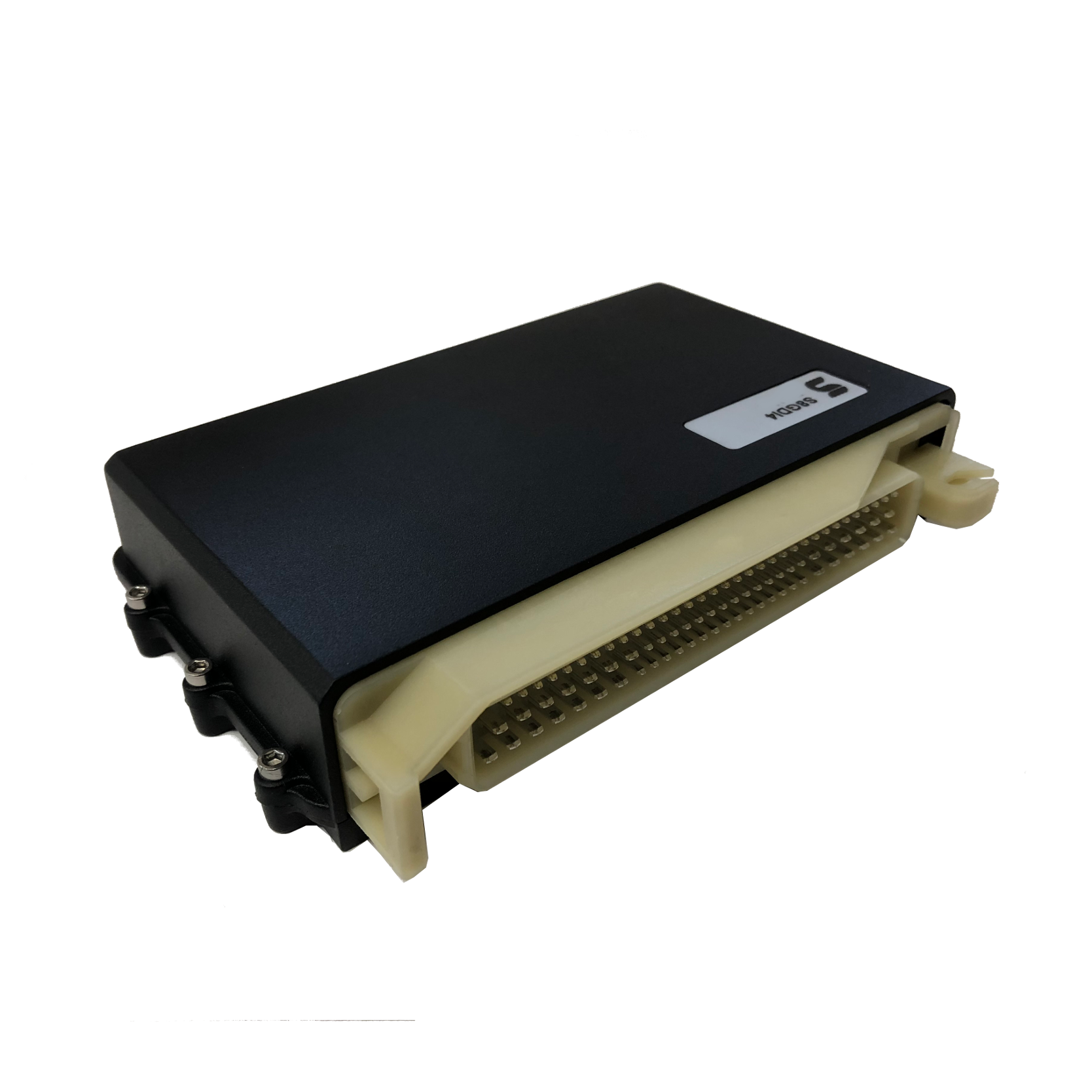
Syvecs S-GDI4 standalone ECU shown as a family illustration; the Fiesta patch harness is not pictured. Kit assignments can differ from the generic ECU wiring. Image: Syvecs, reproduced with permission.
Model and vehicle application
Syvecs lists this vehicle-specific standalone or plug-in ECU kit as Ford Fiesta Mk7 ST180, with product code SGDI-MK7ST. The product page and its stated vehicle, model and transmission details define this particular application; confirm market, model year, engine, ECU connector and transmission against Syvecs before ordering.
This entry describes the dedicated vehicle kit. It is distinct from the generic wire-in ECU: a plug-in kit can use application-specific adaptor wiring, a carrier, additional modules and an application calibration. The listed hardware or supported equipment can vary by revision.
Wiring and pinout
Syvecs Ford Fiesta Mk7 ST180 installation and wiring document. Follow the connector orientation, application-specific tables, installation notes and hardware revision in this document. Do not transfer assignments from another vehicle merely because the underlying ECU family is similar. The link was checked to return a PDF.
For other variants and manual revisions consult the manufacturer's vehicle-specific manual index. Available spare inputs and outputs can be used only within their electrical limits and with a matching calibration.
Calibration and service
Use the correct Syvecs software, firmware and base calibration for the exact vehicle and installed hardware. The Syvecs software portal and firmware archive provide manufacturer support. A base map is a starting point and needs checking against the actual engine, injectors, sensors and modifications.
Sources
Syvecs Ford Fiesta Mk7 ST180 product listing and applicationManufacturer kit installation and pinout manualSyvecs plug-in kit support index
Manufacturer SGDI4 ECU and Fiesta loom mapping
From the Syvecs Ford Fiesta ST Mk7 guide, version 1.0, ECU wiring pages 6–7. The first pin column identifies the Syvecs ECU terminal; the Ford B/E references and loom labels are copied from the guide’s application chart. Empty cells mean the source gives no connection; they do not establish that a cavity is electrically unused. Some labels describe wiring moved between factory positions; verify the installed patch-harness revision and the original diagram.
The diagram also uses a CAN bridge, with the bridge version noted in the relevant rows; the guide depicts vehicle connector positions separately and should be consulted for wire routing and connector orientation.
Rendered revisions
Open each version to inspect formatting, tables and photographs.
Revision 2: Syvecs Ford Fiesta Mk7 ST180 Plug-in ECU
Model and vehicle application
Syvecs lists this vehicle-specific standalone or plug-in ECU kit as Ford Fiesta Mk7 ST180, with product code SGDI-MK7ST. The product page and its stated vehicle, model and transmission details define this particular application; confirm market, model year, engine, ECU connector and transmission against Syvecs before ordering.
This entry describes the dedicated vehicle kit. It is distinct from the generic wire-in ECU: a plug-in kit can use application-specific adaptor wiring, a carrier, additional modules and an application calibration. The listed hardware or supported equipment can vary by revision.
Wiring and pinout
Syvecs Ford Fiesta Mk7 ST180 installation and wiring document. Follow the connector orientation, application-specific tables, installation notes and hardware revision in this document. Do not transfer assignments from another vehicle merely because the underlying ECU family is similar. The link was checked to return a PDF.
For other variants and manual revisions consult the manufacturer's vehicle-specific manual index. Available spare inputs and outputs can be used only within their electrical limits and with a matching calibration.
Calibration and service
Use the correct Syvecs software, firmware and base calibration for the exact vehicle and installed hardware. The Syvecs software portal and firmware archive provide manufacturer support. A base map is a starting point and needs checking against the actual engine, injectors, sensors and modifications.
From the Syvecs Ford Fiesta ST Mk7 guide, version 1.0, ECU wiring pages 6–7. The first pin column identifies the Syvecs ECU terminal; the Ford B/E references and loom labels are copied from the guide’s application chart. Empty cells mean the source gives no connection; they do not establish that a cavity is electrically unused. Some labels describe wiring moved between factory positions; verify the installed patch-harness revision and the original diagram.
SGDI4 pin
Syvecs function
Ford connector / harness reference
Vehicle function
1
Power ground
B96
Power ground
2
Ignition 8
E53
Ign 4
3
Ignition 7
E52
Ign 3
4
Ignition 6
E51
Ign 2
5
Ignition 5
E50
Ign 1
6
Fuel 10
E2
Bypass solenoid
7
Knock 2
E57
Knock 2
8
Input 16 (5V/TH/BI/FREQ)
—
—
9
Input 14 (5V/TH/BI/FREQ)
—
—
10
Input 12 (5V/TH/BI/FREQ)
—
—
11
Input 10 (5V/TH/BI/FREQ)
E36
Intake cam
12
Thermo − 2
—
—
13
Thermo + 2
—
—
14
Input 7 (5V/TH/BI/FREQ)
B8
MAF
15
Input 5 (5V/TH/BI/FREQ)
—
—
16
Input 3 (5V/TH/BI/FREQ)
—
—
17
Input 1 (5V/TH/BI/FREQ)
E35
MAP
18
Lambda V1
E26
Lambda V
19
Input 21 (TH)
E23
ECT
20
Fuel 15
B22
Canister purge
21
RS232 1 TX
—
—
22
Fuel 7
E1
Lambda heater
23
Fuel 5
E16, moved from 30
Cooling fan high speed
24
Ignition 4
E86
GDI 4+
25
Ignition 3
E92
GDI 3+
26
Ignition 2
E87
GDI 2+
27
Ignition 1
E91
GDI 1+
28
Power ground
B97
Ground
29
Power ground
B99 + CAN bridge V2 pin 3
Ground
30
Fuel 14
B5, moved from 23
VVT exhaust
31
Fuel 13
B43, moved from 50
VVT intake
32
Fuel 12 / GDI pump −
E78
Fuel volume control −
33
Fuel 11
E48
Turbo bypass
34
Fuel 9
—
—
35
Knock 1
E59
—
36
Input 15 (5V/TH/BI/FREQ)
E42
Oil pressure switch
37
Input 13 (5V/TH/BI/FREQ)
B45
PPS (PWM)
38
Input 11 (5V/TH/BI/FREQ)
E37
Exhaust cam
39
Input 9 (5V/TH/BI/FREQ)
E49
Crank
40
Thermo − 1
—
—
41
Input 8 (5V/TH/BI/FREQ)
B30
Clutch switch
42
Input 6 (5V/TH/BI/FREQ)
B66
Brake switch
43
Input 4 (5V/TH/BI/FREQ)
B52
A/C pressure
44
Input 2 (5V/TH/BI/FREQ)
E38
FP
45
CAN low 3
—
—
46
Input 22 (TH)
—
—
47
Fuel 16
E47
Boost solenoid
48
RS232 RX
—
—
49
Fuel 8
B2
A/C clutch
50
Fuel 6
E31, moved from 31
Starter relay ground
51
Fuel 4
E83
GDI 4− (spare)
52
Fuel 3
E82
GDI 3−
53
Fuel 2
E81
GDI 2−
54
Fuel 1
E84
GDI 1−
55
Power ground
Relay 30 & 86
—
56
Battery supply
B101, B102
VBATT
57
Battery supply
B103; CAN bridge V2 pin 12
VBATT
58
H-bridge 1
E94
DBW+
59
H-bridge 2
E89
DBW−
60
H-bridge 3
B39
Fuel pump ECU
61
H-bridge 4
E79
Fuel volume control +
62
10 V output
—
—
63
5 V output 2
—
—
64
5 V output 1
B14; E3, E5, E7
A/C, MAP, brake vacuum, crank, TPS
65
Knock ground
E58, E60
—
66
Input 20 (5V/knock 4)
B71
Low fuel pressure
67
Sensor ground 2
B9, B17, B19
A/C, clutch switch, MAF
68
Input 19 (5V/knock 3)
—
—
69
Sensor ground 1
—
—
70
Thermo + 1
—
—
71
Input 18 (5V)
E34
TPS2
72
Sensor ground 2
—
—
73
Input 17 (5V)
E33
TPS1
74
Sensor ground 1
E10, E18, E19, E20, E22, E54
TPS, MAP, VVT, FP
75
CAN high 3
—
—
76
Lambda I1
E39
—
77
Lambda ground
E25
—
78
Communications ground
—
—
79
CAN low 2
—
—
80
CAN high 2
—
—
81
CAN low 1
CAN bridge pin 6
—
82
CAN high 1
CAN bridge pin 15
—
83
Input 24 (TH)
B75
IAT
84
Input 23 (TH)
B32
ACT
85
LAN RX+
White/orange
Ethernet socket
86
LAN RX−
Orange/white
Ethernet socket
87
LAN TX+
White/green
Ethernet socket
88
LAN TX−
Green/white
Ethernet socket
The diagram also uses a CAN bridge, with the bridge version noted in the relevant rows; the guide depicts vehicle connector positions separately and should be consulted for wire routing and connector orientation.
Revision 3: Syvecs Ford Fiesta Mk7 ST180 Plug-in ECUSyvecs S-GDI4 standalone ECU shown as a family illustration; the Fiesta patch harness is not pictured. Kit assignments can differ from the generic ECU wiring. Image: Syvecs, reproduced with permission.
Model and vehicle application
Syvecs lists this vehicle-specific standalone or plug-in ECU kit as Ford Fiesta Mk7 ST180, with product code SGDI-MK7ST. The product page and its stated vehicle, model and transmission details define this particular application; confirm market, model year, engine, ECU connector and transmission against Syvecs before ordering.
This entry describes the dedicated vehicle kit. It is distinct from the generic wire-in ECU: a plug-in kit can use application-specific adaptor wiring, a carrier, additional modules and an application calibration. The listed hardware or supported equipment can vary by revision.
Wiring and pinout
Syvecs Ford Fiesta Mk7 ST180 installation and wiring document. Follow the connector orientation, application-specific tables, installation notes and hardware revision in this document. Do not transfer assignments from another vehicle merely because the underlying ECU family is similar. The link was checked to return a PDF.
For other variants and manual revisions consult the manufacturer's vehicle-specific manual index. Available spare inputs and outputs can be used only within their electrical limits and with a matching calibration.
Calibration and service
Use the correct Syvecs software, firmware and base calibration for the exact vehicle and installed hardware. The Syvecs software portal and firmware archive provide manufacturer support. A base map is a starting point and needs checking against the actual engine, injectors, sensors and modifications.
From the Syvecs Ford Fiesta ST Mk7 guide, version 1.0, ECU wiring pages 6–7. The first pin column identifies the Syvecs ECU terminal; the Ford B/E references and loom labels are copied from the guide’s application chart. Empty cells mean the source gives no connection; they do not establish that a cavity is electrically unused. Some labels describe wiring moved between factory positions; verify the installed patch-harness revision and the original diagram.
SGDI4 pin
Syvecs function
Ford connector / harness reference
Vehicle function
1
Power ground
B96
Power ground
2
Ignition 8
E53
Ign 4
3
Ignition 7
E52
Ign 3
4
Ignition 6
E51
Ign 2
5
Ignition 5
E50
Ign 1
6
Fuel 10
E2
Bypass solenoid
7
Knock 2
E57
Knock 2
8
Input 16 (5V/TH/BI/FREQ)
—
—
9
Input 14 (5V/TH/BI/FREQ)
—
—
10
Input 12 (5V/TH/BI/FREQ)
—
—
11
Input 10 (5V/TH/BI/FREQ)
E36
Intake cam
12
Thermo − 2
—
—
13
Thermo + 2
—
—
14
Input 7 (5V/TH/BI/FREQ)
B8
MAF
15
Input 5 (5V/TH/BI/FREQ)
—
—
16
Input 3 (5V/TH/BI/FREQ)
—
—
17
Input 1 (5V/TH/BI/FREQ)
E35
MAP
18
Lambda V1
E26
Lambda V
19
Input 21 (TH)
E23
ECT
20
Fuel 15
B22
Canister purge
21
RS232 1 TX
—
—
22
Fuel 7
E1
Lambda heater
23
Fuel 5
E16, moved from 30
Cooling fan high speed
24
Ignition 4
E86
GDI 4+
25
Ignition 3
E92
GDI 3+
26
Ignition 2
E87
GDI 2+
27
Ignition 1
E91
GDI 1+
28
Power ground
B97
Ground
29
Power ground
B99 + CAN bridge V2 pin 3
Ground
30
Fuel 14
B5, moved from 23
VVT exhaust
31
Fuel 13
B43, moved from 50
VVT intake
32
Fuel 12 / GDI pump −
E78
Fuel volume control −
33
Fuel 11
E48
Turbo bypass
34
Fuel 9
—
—
35
Knock 1
E59
—
36
Input 15 (5V/TH/BI/FREQ)
E42
Oil pressure switch
37
Input 13 (5V/TH/BI/FREQ)
B45
PPS (PWM)
38
Input 11 (5V/TH/BI/FREQ)
E37
Exhaust cam
39
Input 9 (5V/TH/BI/FREQ)
E49
Crank
40
Thermo − 1
—
—
41
Input 8 (5V/TH/BI/FREQ)
B30
Clutch switch
42
Input 6 (5V/TH/BI/FREQ)
B66
Brake switch
43
Input 4 (5V/TH/BI/FREQ)
B52
A/C pressure
44
Input 2 (5V/TH/BI/FREQ)
E38
FP
45
CAN low 3
—
—
46
Input 22 (TH)
—
—
47
Fuel 16
E47
Boost solenoid
48
RS232 RX
—
—
49
Fuel 8
B2
A/C clutch
50
Fuel 6
E31, moved from 31
Starter relay ground
51
Fuel 4
E83
GDI 4− (spare)
52
Fuel 3
E82
GDI 3−
53
Fuel 2
E81
GDI 2−
54
Fuel 1
E84
GDI 1−
55
Power ground
Relay 30 & 86
—
56
Battery supply
B101, B102
VBATT
57
Battery supply
B103; CAN bridge V2 pin 12
VBATT
58
H-bridge 1
E94
DBW+
59
H-bridge 2
E89
DBW−
60
H-bridge 3
B39
Fuel pump ECU
61
H-bridge 4
E79
Fuel volume control +
62
10 V output
—
—
63
5 V output 2
—
—
64
5 V output 1
B14; E3, E5, E7
A/C, MAP, brake vacuum, crank, TPS
65
Knock ground
E58, E60
—
66
Input 20 (5V/knock 4)
B71
Low fuel pressure
67
Sensor ground 2
B9, B17, B19
A/C, clutch switch, MAF
68
Input 19 (5V/knock 3)
—
—
69
Sensor ground 1
—
—
70
Thermo + 1
—
—
71
Input 18 (5V)
E34
TPS2
72
Sensor ground 2
—
—
73
Input 17 (5V)
E33
TPS1
74
Sensor ground 1
E10, E18, E19, E20, E22, E54
TPS, MAP, VVT, FP
75
CAN high 3
—
—
76
Lambda I1
E39
—
77
Lambda ground
E25
—
78
Communications ground
—
—
79
CAN low 2
—
—
80
CAN high 2
—
—
81
CAN low 1
CAN bridge pin 6
—
82
CAN high 1
CAN bridge pin 15
—
83
Input 24 (TH)
B75
IAT
84
Input 23 (TH)
B32
ACT
85
LAN RX+
White/orange
Ethernet socket
86
LAN RX−
Orange/white
Ethernet socket
87
LAN TX+
White/green
Ethernet socket
88
LAN TX−
Green/white
Ethernet socket
The diagram also uses a CAN bridge, with the bridge version noted in the relevant rows; the guide depicts vehicle connector positions separately and should be consulted for wire routing and connector orientation.