A dynamometer controller regulates the load applied to the engine or vehicle and may also operate the throttle and record test data. It does not determine the dyno type by itself: an electronic controller can command an eddy-current brake, a water valve, a hydrostatic system or an electrical machine, each with different physical limits. Start with Dynamometers.

Manual and older controls
A basic manual system uses an operator, speed indication, a torque display and a valve or electrical field control. The operator changes the load while observing the engine. Mechanical linkages, separate analogue indicators and chart recorders can be found on older installations. Manual control can perform a steady test, but maintaining a repeatable target depends heavily on operator response.
Automatic feedback is not exclusively digital or new. A historical University of Edinburgh review describes a 1950 electronic road-load simulation using a speed generator, analogue control channels and an amplifier controlling dynamometer field current. It also discusses open-loop programmed cycles and feedback-based approaches. University of Edinburgh dynamometer control research.
Closed-loop operation
- A speed pickup and often a load cell or shaft-torque sensor report the current condition.
- The controller compares the measured value with the requested speed or torque (the setpoint).
- It adjusts an output such as field current, a water or oil valve, or an inverter torque command.
- The process repeats as the engine and absorber respond. A separate throttle actuator or operator controls engine output where required.
A proportional-integral (PI) or proportional-integral-derivative (PID) controller is one common approach; tuning affects response, overshoot and stability. Filtering, actuator limits, delays and changing operating conditions matter. Modern systems can use other strategies, scheduled control parameters or feed-forward. An actual eddy-current engine control study compares several approaches. Active control of an engine dynamometer.
Common test modes
- Manual load: operator sets the actuator; speed and torque result from the interaction of engine and absorber.
- Speed hold: absorber load is adjusted to maintain a chosen speed as the throttle or engine torque changes. Useful for steady-state fuel and ignition mapping when the absorber can supply the necessary torque.
- Torque or load hold: feedback targets the configured torque measurement. Engine throttle and load interact; the controller arrangement must provide a viable operating point rather than assume independent speed and torque control.
- Sweep or ramp: speed changes over a defined range and rate, or according to available power and inertia. The exact mode and compensation differ between systems.
- Road-load simulation: a model commands resistance based on speed and possibly acceleration or a recorded drive cycle. An absorber-only machine cannot reproduce every downhill, overrun or externally driven condition; motoring requires suitable hardware.
Measurements and safeguards
Torque transducers require zero and calibration checks; speed sensing, gearing, roller diameter, sample rate and channel timing must match the test. Load-cell reaction torque is not necessarily total engine torque during acceleration because rotating inertia and losses also matter. Report the measurement location, test mode, environmental correction and any estimated drivetrain losses with results.
Controller output is constrained by actuator, machine torque–speed and heat-rejection limits. A target outside the envelope cannot be held regardless of software. Overspeed, loss of cooling, sensor faults, failed communications and emergency stop need a machine-specific safe response. A dyno controller does not replace proper restraints, guarding, ventilation and manufacturer procedures.
Manufacturers, suppliers and retrofit examples
These examples illustrate different routes to a modern controller. Product capabilities and retrofit compatibility depend on the specific hardware, sensors, brake and installation; confirm them with the supplier.
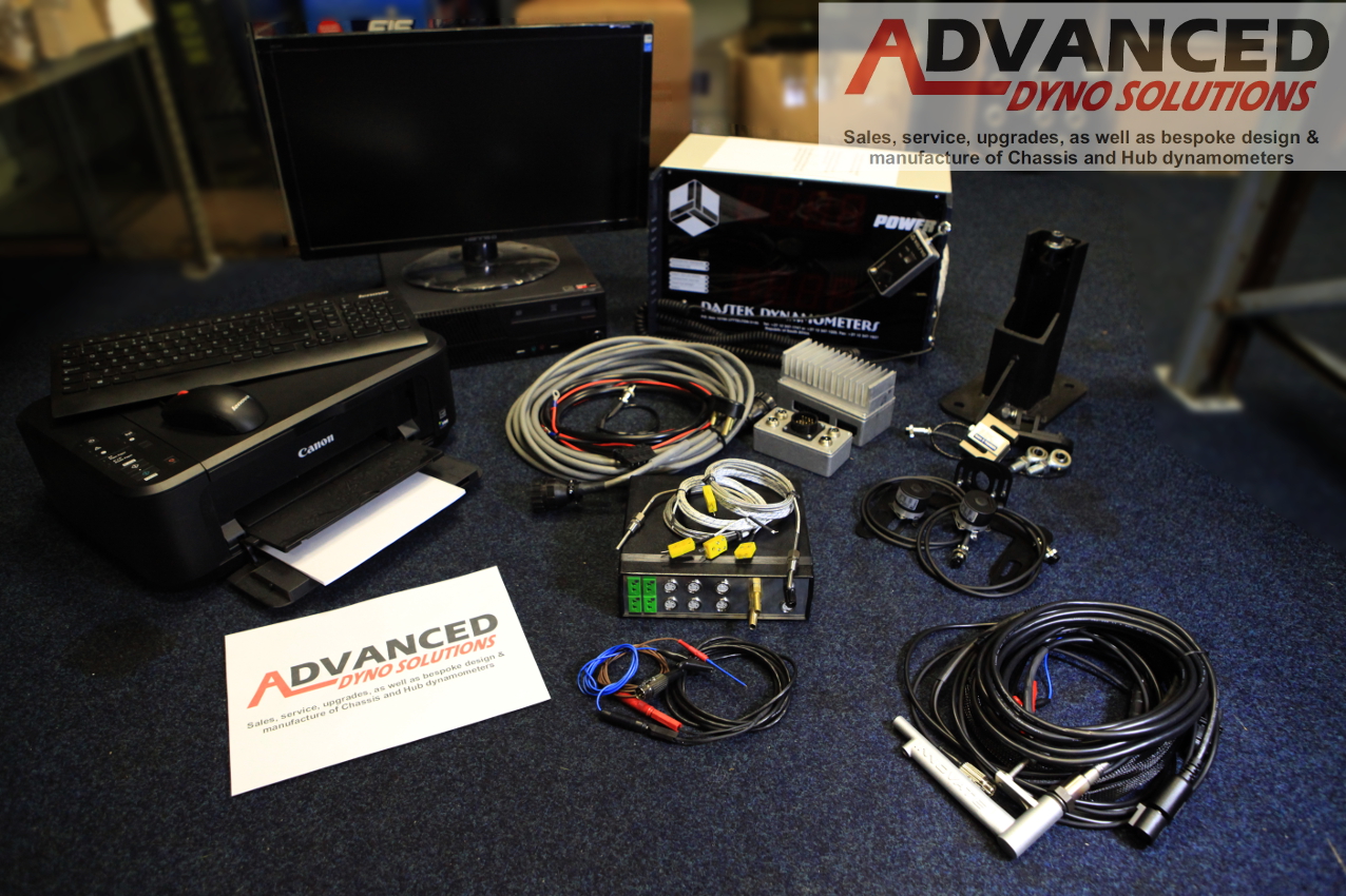
- Advanced Dyno Solutions: Dastek 2WD controller upgrade — a supplier offering a Dastek controller package for an existing two-wheel-drive dyno; ADS also lists 4WD upgrades and SportDevices accessories.
- PEREK DC2 — a controller and data-acquisition system described by the manufacturer for rolling-road and hub dynos, with configurations for inertial, eddy-current and water-brake applications. Its retrofit guide discusses speed pickups, load cells and brake control.
- SuperFlow WinDyn5 — a test-cell acquisition and control platform with configurable channels, profiles and PID control for supported dynamometers.
- Power Test / Taylor load-control assemblies — interfaces using water valves or an eddy-brake current amplifier, illustrating how controller signals reach different absorbers.
Sources
- University of Edinburgh: dynamometer control research, historical review.
- Active control of an engine dynamometer, feedback and PI/PID comparison.
- Closed-loop torque and speed control on an eddy-current dynamometer, throttle and absorber control example.
Related company profiles
SportDevices · YourDyno · PEREK · Dastek · Froude.