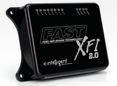
FAST XFI 2.0 programmable fuel-and-ignition controller and optioned variants.
Identification and functions
FAST lists sequential or bank-to-bank fuel control, four switch-selectable calibrations, boost and progressive nitrous strategies, individual-cylinder correction and CAN integration. Internal logging, traction control and marine configuration depend on the ordered unit. The manufacturer's XFI 2.0 listing identifies 301000 base, 301006 traction/16-injector option, 301007 traction/logging, 301008 traction/logging/16-injector option and 301015 marine. The FAST 2016 catalogue additionally identifies 301003 logging, 301004 logging/16-injector and 301005 traction variants. For the exact unit consult the XFI installation and connector manual and C-Com software archive; confirm whether the ECU has been upgraded and whether options are enabled.
Wiring and support
Identify ECU part number, software version, harness and engine before connecting inputs or outputs. Exact pin functions depend on the specific unit, harness and optional drivers. FAST's software and documentation index separates its families. A missing pinout is not evidence that a related system uses the same connector.
See the FAST manufacturer index. Sources reviewed 17 November 2026.
Manufacturer connector schedules
FAST lists its 301100 main harness for both XFI and XFI 2.0. The following schedule is the original XFI chart and 301100 harness diagram; verify the actual XFI 2.0 part, harness and options, as this does not document every possible model variant. The FAST XFI installation manual, PDF pages 14–16 and the 301100 harness schematic on page 164, lists 32 A, 25 B, 31 C and 16 D positions. Asterisks reproduce the manual's high-current pin notation; a dash denotes a blank colour in the source, not an unused circuit. Harness colours and downstream connector letters can vary with the loom. Identify connector orientation and hardware before wiring.
ECU connector A
| ECU pin | Documented function | Harness wire colour |
|---|---|---|
| A1* | Inductive Cam Pickup Return (Ground) | Black |
| A2* | Inductive Crank Pickup Return (Ground) | Black |
| A3 | Inductive Cam Positive Input Signal | Red |
| A4 | Inductive Crank Positive Input Signal | Red |
| A5 | Discrete Vehicle Speed Sensor Input Signal | White (B) |
| A6 | Discrete Auxiliary Speed Sensor Input Signal | Orange (B) |
| A7 | Discrete Cam Pickup Input Signal | Ylw / Blk (C ) |
| A8 | Discrete Crank Pickup Input Signal | Brn / Wht (F) |
| A9 | Knock Input Signal (ESC) | Black (C) |
| A10 | TFI / EDIS Ignition Output (TFI/SAW) | Blu / Wht (H) |
| A11 | Points Ignition Output (POINTS) | White |
| A12* | Main Power Return (Ground) | Black (10 ga) |
| A13* | Distributor Return (Ground) | Blk / Wht (D) |
| A14 | HEI Ignition Output (EST) | Tan / Blk (E) |
| A15 | Crank / Run Mode Output (BYPASS) | Grn / Lt Grn (G ) |
| A16 | Inductive Vehicle Speed Sensor Positive Input Signal | Yellow (C ) |
| A17 | Inductive Auxiliary Speed Sensor Positive Input Signal | Violet (D) |
| A18 | Pulse Width Modulated (PWM) Output #2 | — |
| A19 | Pulse Width Modulated (PWM) Output #1 | — |
| A20 | Clutch Input Signal | — |
| A21 | Flash Programming Enable Input Signal | Blue (A) |
| A22 | Calibration Select Switch Input #1 | Gray (B) |
| A23 | Calibration Select Switch Input #0 | Yellow (C ) |
| A24 | A/C Idle Increase Input Signal | — |
| A25* | Digital Auxiliary Input Signal #0 | — |
| A26 | Digital Auxiliary Input Signal #1 | — |
| A27 | Digital Auxiliary Input Signal #2 | — |
| A28 | Digital Auxiliary Input Signal #3 | — |
| A29 | Digital Auxiliary Input Signal #4 | — |
| A30 | Digital Auxiliary Input Signal #5 | — |
| A31 | Digital Auxiliary Input Signal #6 | — |
| A32 | Digital Auxiliary Input Signal #7 | — |
ECU connector B
| ECU pin | Documented function | Harness wire colour |
|---|---|---|
| B1 | Auxiliary Switched Output #1 | — |
| B2 | Auxiliary Switched Output #2 | — |
| B3 | Auxiliary Switched Output #3 | — |
| B4 | Auxiliary Switched Output #4 | — |
| B5 | Fuel Pump Control Output | Black |
| B6 | Torque Converter Clutch (TCC) Control Output | — |
| B7* | Main Power Return (Ground) | Black 10gage |
| B8* | Digital Inputs Return (Ground) | Black |
| B9 | Service Engine Soon (SES) Lamp Output | Lt Green (D) |
| B10 | Fan Control Output | Black |
| B11 | A/C Enable Output | — |
| B12 | Idle Air Control (IAC) Output A Hi | Red (A) |
| B13 | Idle Air Control (IAC) Output A Lo | Blue (B) |
| B14 | Idle Air Control (IAC) Output B Hi | Ylw (C ) |
| B15 | Idle Air Control (IAC) Output B Lo | Black (D) |
| B16 | Power Adder Hold Enable Input | Pink (E) |
| B17* | Switched Ignition Voltage Input | Pink (Sw Ign) |
| B18* | Battery Voltage Input | Red (Batt 3 Amp) |
| B19 | Power Adder Enable Input | Pink (F) |
| B20 | Power Adder Switched Output #1 | Blu / Wht (A) |
| B21 | Power Adder Switched Output #2 | Blu / Ylw (B) |
| B22 | Power Adder Switched Output #3 | Blu / Grn (C ) |
| B23 | Power Adder Switched Output #4 | Blu / Orn (D) |
| B24* | Analog Inputs Return (Ground) | Black |
| B25* | Main Power Return (Ground) | Black |
ECU connector C
| ECU pin | Documented function | Harness wire colour |
|---|---|---|
| C1 | UEGOP+ | White (B) |
| C2 | UEGOP- | Black (A) |
| C3 | UEGOS+ | Red (C ) |
| C4 | UEGOR+ | Gray (E) |
| C5 | UEGOR- | Blue (F) |
| C6 | UEGOH- | Yellow (G) |
| C7 | Pulse Width Modulated (PWM) Output #3 (EGR Control) | — |
| C8 | Pulse Width Modulated (PWM) Output #4 (Boost Control) | Brown |
| C9 | Controller Area Network (CAN) #1 High Signal | — |
| C10 | Controller Area Network (CAN) #1 Low Signal | — |
| C11 | Analog Auxiliary Input Return (Ground) | Black (K) |
| C12 | Analog Auxiliary Input Signal #1 | Blu / Gra (A) |
| C13 | Analog Auxiliary Input Signal #2 | Gray (B) |
| C14 | Analog Auxiliary Input Signal #3 | Violet(C ) |
| C15 | Analog Auxiliary Input Signal #4 | Lt Green (D) |
| C16 | Analog Auxiliary Input Signal #5 | Ylw / Blk (E) |
| C17 | Analog Auxiliary Input Signal #6 | Blue (F) |
| C18 | Analog Auxiliary Input Signal #7 | Brn / Wht (G) |
| C19 | Analog Auxiliary Input Signal #8 | White (H) |
| C20 | Manifold Absolute Pressure (MAP) Sensor Input Signal | Wht / Vio (B) |
| C21 | Throttle Position Sensor (TPS) Input Signal | Wht / Red (B) |
| C22 | Air Temp Sensor (ATS) Input Signal | Wht / Pnk (A) |
| C23 | Coolant Temperature Sensor (CTS) Input Signal | White (A) |
| C24 | 5 Volt Reference Output | Red (5 volt ref) |
| C25 | Controller Area Network (CAN) #0 High Signal | — |
| C26 | Controller Area Network (CAN) #0 Low Signal | — |
| C27 | RS-232 PC Communications Transmit #0 | Red (A) |
| C28 | RS-232 PC Communications Receive #0 | Black (C) |
| C29 | RS-232 Communications Return (Ground) | White (B) |
| C30 | RS-232 PC Communications Transmit #1 | — |
| C31 | RS-232 PC Communications Receive #1 | — |
ECU connector D
| ECU pin | Documented function | Harness wire colour |
|---|---|---|
| D1* | Main Power Return (Ground) | Black (10ga) |
| D2 | Injector Output A | Black (A) |
| D3 | Main Power Return (Ground) | — |
| D4 | Injector Output B | Brown (B) |
| D5 | Main Power Return (Ground) | — |
| D6* | Main Power Return (Ground) | — |
| D7 | Injector Output C | Yellow (C) |
| D8 | Main Power Return (Ground) | — |
| D9 | Injector Output D | Green (D) |
| D10 | Main Power Return (Ground) | — |
| D11 | Injector Output E | Orange (E) |
| D12 | Main Power Return (Ground) | — |
| D13 | Injector Output F | Blue (F) |
| D14 | Injector Output G | Gray (G) |
| D15 | Main Power Return (Ground) | — |
| D16 | Injector Output H | Violet (H) |