Tuning Wiki

This is a historical revision. Read the current page or return to its history.

Page organisation in this revision
Page type
Reference hub
Subject
Engine ECU
Parent
Autronic standalone ECUs
Applies to
No ECU-specific applicability
Tool groups
None
Manufacturers
None

Changes from revision 3 to revision 5

Removed text is struck through; added text is highlighted.

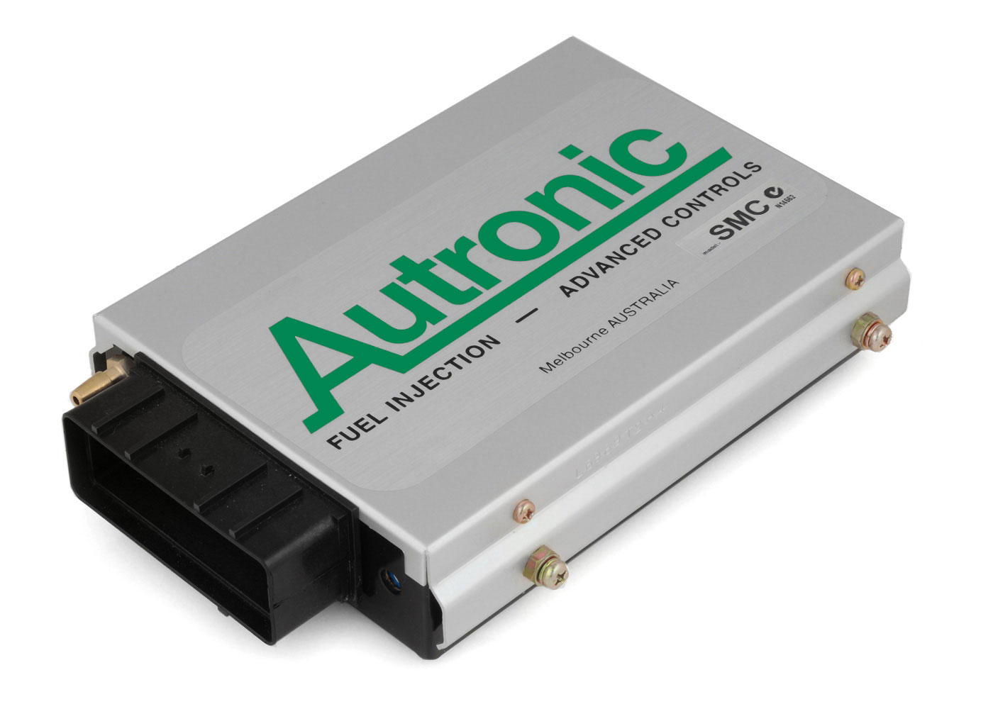
Autronic SMC. Image: Autronic product page, reproduced with permission.

Autronic SMC is a standalone or earlier programmable engine-management system. Early SMC sequential engine management. Autronic distinguishes pre-1996 and later Rev C loom arrangements; its archive says early looms only suit pre-1996 ECUs. Model-specific information.

Identification and features

Record the ECU label, model, part number, hardware revision, firmware, configured injectors, ignition hardware and loom before comparing systems. Some outputs can be reassigned; hardware, software, current limits and engine-specific options determine what is actually available.

ProcessorAutronic's product page (manufacturer documentation) gives the SMC microcontroller as a 16-bit Intel part running at 16 MHz. The exact part number is not stated in the sources checked.Engine applicationsThe SMC is a universal ECU, not tied to specific vehicles. Per Autronic it suits port-injected spark-ignition engines without drive-by-wire throttle or feedback-controlled variable camshafts, including high-output supercharged or turbocharged engines, two-stroke engines, and engines with uneven firing sequences such as two- and four-cylinder V motorcycle engines and V6 car engines. Selectable cylinder counts are 1 to 8, 10, 12, 14 and 16, with full sequential injection for 2 to 8 cylinders. Hardware: eight injector drivers (selectable 4 A/1 A or 2 A/0.5 A), four open-collector ignition outputs without dwell control on the standard unit, one auxiliary output, fuel pump control, RS232 serial and a 36-way AMP connector. Positioned for high-performance motorsport; no engine codes are listed.

Wiring and pinout

Consult the Autronic SMC wiring and documentation source and identify the exact connector face, part and version. Do not apply wiring from a similarly named model. If an exact drawing is unavailable for the unit at hand, obtain it from the manufacturer or supplier before making connections.

J1 connector: manufacturer loom drawingsThe 36-position J1 table, transcribed from Autronic's Type 1 pre-1996 single-relay diagram, revision 003 and universal Type 2 Rev C single-relay diagram, revision 005, with the pin 21 and 34 differences between the looms and the drawing wire colours, is on the Autronic SMC connector pinout page with a redrawn pin-index diagram (diagram redrawn by Tuning Wiki). The Type 1 loom is specified only for ECUs manufactured before 1996; the Type 2 drawing states it suits all SMC ECUs. Autronic's drawings call for calibration mode flag 11 to be set to 1 for the illustrated relay arrangement; the auxiliary and ignition output capabilities depend on the hardware and firmware fitted.J1 pinType 1 pre-1996 drawingType 2 Rev C universal drawingDrawing wire colour1Injector 7 outputInjector 7 outputGrey/blue2Injector 6 outputInjector 6 outputBlue/black3Injector 4 outputInjector 4 outputGreen/white4Injector 2 outputInjector 2 outputOrange/black5Injector 1 outputInjector 1 outputPink/black6Coolant temperature inputCoolant temperature inputPink7O2 inputO2 inputBlue8Reference trigger inputReference trigger inputGreen9Serial RXSerial RXPurple10Ignition 4 outputIgnition 4 outputNot specified11Ignition 2 outputIgnition 2 outputNot specified12Auxiliary outputAuxiliary outputGrey13ECU +12 V supplyECU +12 V supplyRed14Injector 8 outputInjector 8 outputBlue/red15Injector 5 outputInjector 5 outputGreen/yellow16Injector 3 outputInjector 3 outputBlue/white17Sensor groundSensor groundBlack18Throttle position inputThrottle position inputOrange19Throttle position supplyThrottle position supplyRed/white20Trigger supplyTrigger supplyRed/black21Serial I/O groundSwitch inputBlack / green-orange respectively22Ignition 3 outputIgnition 3 outputNot specified23Diagnostic output (optional connection)Diagnostic output (optional connection)Not specified24Fuel pump outputFuel pump outputBlue25+12 V / pump relay supply+12 V / pump relay supplyRed26+12 V / auxiliary output supply+12 V / auxiliary output supplyPink/yellow27ECU groundECU groundBlack28ECU groundECU groundBlack29Ignition switch inputIgnition switch inputRed30Intake air temperature inputIntake air temperature inputWhite31Trigger groundTrigger groundBlack32Cylinder pulse trigger inputCylinder pulse trigger inputYellow33Serial TXSerial TXOrange34Not labelled on Type 1 drawingSerial I/O groundNot specified / black respectively35Ignition 1 outputIgnition 1 outputPink/white36Ignition output groundIgnition output groundNot specified

Further information

Autronic SMC model informationWiring, manuals or technical archiveAutronic manufacturer index

SourcesAutronic SMC product page. Manufacturer. Accessed 19 November 2026.SMC loom, pre-1996 Type 1, revision 003 and Type 2 Rev C, revision 005. Manufacturer drawings. Accessed 19 November 2026.J1 connector: manufacturer loom drawingsTranscribed from Autronic's Type 1 pre-1996 single-relay diagram, revision 003 and universal Type 2 Rev C single-relay diagram, revision 005. Both diagrams are linked from the manufacturer's SMC model page. The Type 1 loom is specified only for ECUs manufactured before 1996; the Type 2 drawing states it suits all SMC ECUs. The differences at pins 21 and 34 are preserved explicitly. Check the connector drawing, unit date, loom type, firmware and options before wiring.J1 is drawn with pins 1, 13 and 25 at one end and 12, 24 and 36 at the opposite end. The optional diagnostic connection is shown dashed. “Not labelled” does not establish that a cavity is electrically unused. Colours apply to the depicted manufacturer looms; uncoloured ignition and diagnostic wiring is not specified in the drawings.J1 pinType 1 pre-1996 drawingType 2 Rev C universal drawingDrawing wire colour1Injector 7 outputInjector 7 outputGrey/blue2Injector 6 outputInjector 6 outputBlue/black3Injector 4 outputInjector 4 outputGreen/white4Injector 2 outputInjector 2 outputOrange/black5Injector 1 outputInjector 1 outputPink/black6Coolant temperature inputCoolant temperature inputPink7O2 inputO2 inputBlue8Reference trigger inputReference trigger inputGreen9Serial RXSerial RXPurple10Ignition 4 outputIgnition 4 outputNot specified11Ignition 2 outputIgnition 2 outputNot specified12Auxiliary outputAuxiliary outputGrey13ECU +12 V supplyECU +12 V supplyRed14Injector 8 outputInjector 8 outputBlue/red15Injector 5 outputInjector 5 outputGreen/yellow16Injector 3 outputInjector 3 outputBlue/white17Sensor groundSensor groundBlack18Throttle position inputThrottle position inputOrange19Throttle position supplyThrottle position supplyRed/white20Trigger supplyTrigger supplyRed/black21Serial I/O groundSwitch inputBlack / green-orange respectively22Ignition 3 outputIgnition 3 outputNot specified23Diagnostic output (optional connection)Diagnostic output (optional connection)Not specified24Fuel pump outputFuel pump outputBlue25+12 V / pump relay supply+12 V / pump relay supplyRed26+12 V / auxiliary output supply+12 V / auxiliary output supplyPink/yellow27ECU groundECU groundBlack28ECU groundECU groundBlack29Ignition switch inputIgnition switch inputRed30Intake air temperature inputIntake air temperature inputWhite31Trigger groundTrigger groundBlack32Cylinder pulse trigger inputCylinder pulse trigger inputYellow33Serial TXSerial TXOrange34Not labelled on Type 1 drawingSerial I/O groundNot specified / black respectively35Ignition 1 outputIgnition 1 outputPink/white36Ignition output groundIgnition output groundNot specifiedAutronic’s drawings call for calibration mode flag 11 to be set to 1 for the illustrated relay arrangement. Check the source and the ECU’s actual configuration; the auxiliary and ignition output capabilities depend on the hardware and firmware fitted.

Rendered revisions

Open each version to inspect formatting, tables and photographs.

Revision 3: Autronic SMC
Autronic SMC ECU
Autronic SMC. Image: Autronic product page, reproduced with permission.

Autronic SMC is a standalone or earlier programmable engine-management system. Early SMC sequential engine management. Autronic distinguishes pre-1996 and later Rev C loom arrangements; its archive says early looms only suit pre-1996 ECUs. Model-specific information.

Identification and features

Record the ECU label, model, part number, hardware revision, firmware, configured injectors, ignition hardware and loom before comparing systems. Some outputs can be reassigned; hardware, software, current limits and engine-specific options determine what is actually available.

Wiring and pinout

Consult the Autronic SMC wiring and documentation source and identify the exact connector face, part and version. Do not apply wiring from a similarly named model. If an exact drawing is unavailable for the unit at hand, obtain it from the manufacturer or supplier before making connections.

Further information

J1 connector: manufacturer loom drawings

Transcribed from Autronic's Type 1 pre-1996 single-relay diagram, revision 003 and universal Type 2 Rev C single-relay diagram, revision 005. Both diagrams are linked from the manufacturer's SMC model page. The Type 1 loom is specified only for ECUs manufactured before 1996; the Type 2 drawing states it suits all SMC ECUs. The differences at pins 21 and 34 are preserved explicitly. Check the connector drawing, unit date, loom type, firmware and options before wiring.

J1 is drawn with pins 1, 13 and 25 at one end and 12, 24 and 36 at the opposite end. The optional diagnostic connection is shown dashed. “Not labelled” does not establish that a cavity is electrically unused. Colours apply to the depicted manufacturer looms; uncoloured ignition and diagnostic wiring is not specified in the drawings.

J1 pinType 1 pre-1996 drawingType 2 Rev C universal drawingDrawing wire colour
1Injector 7 outputInjector 7 outputGrey/blue
2Injector 6 outputInjector 6 outputBlue/black
3Injector 4 outputInjector 4 outputGreen/white
4Injector 2 outputInjector 2 outputOrange/black
5Injector 1 outputInjector 1 outputPink/black
6Coolant temperature inputCoolant temperature inputPink
7O2 inputO2 inputBlue
8Reference trigger inputReference trigger inputGreen
9Serial RXSerial RXPurple
10Ignition 4 outputIgnition 4 outputNot specified
11Ignition 2 outputIgnition 2 outputNot specified
12Auxiliary outputAuxiliary outputGrey
13ECU +12 V supplyECU +12 V supplyRed
14Injector 8 outputInjector 8 outputBlue/red
15Injector 5 outputInjector 5 outputGreen/yellow
16Injector 3 outputInjector 3 outputBlue/white
17Sensor groundSensor groundBlack
18Throttle position inputThrottle position inputOrange
19Throttle position supplyThrottle position supplyRed/white
20Trigger supplyTrigger supplyRed/black
21Serial I/O groundSwitch inputBlack / green-orange respectively
22Ignition 3 outputIgnition 3 outputNot specified
23Diagnostic output (optional connection)Diagnostic output (optional connection)Not specified
24Fuel pump outputFuel pump outputBlue
25+12 V / pump relay supply+12 V / pump relay supplyRed
26+12 V / auxiliary output supply+12 V / auxiliary output supplyPink/yellow
27ECU groundECU groundBlack
28ECU groundECU groundBlack
29Ignition switch inputIgnition switch inputRed
30Intake air temperature inputIntake air temperature inputWhite
31Trigger groundTrigger groundBlack
32Cylinder pulse trigger inputCylinder pulse trigger inputYellow
33Serial TXSerial TXOrange
34Not labelled on Type 1 drawingSerial I/O groundNot specified / black respectively
35Ignition 1 outputIgnition 1 outputPink/white
36Ignition output groundIgnition output groundNot specified

Autronic’s drawings call for calibration mode flag 11 to be set to 1 for the illustrated relay arrangement. Check the source and the ECU’s actual configuration; the auxiliary and ignition output capabilities depend on the hardware and firmware fitted.

Revision 5: Autronic SMC
Autronic SMC ECU
Autronic SMC. Image: Autronic product page, reproduced with permission.

Autronic SMC is a standalone or earlier programmable engine-management system. Early SMC sequential engine management. Autronic distinguishes pre-1996 and later Rev C loom arrangements; its archive says early looms only suit pre-1996 ECUs. Model-specific information.

Identification and features

Record the ECU label, model, part number, hardware revision, firmware, configured injectors, ignition hardware and loom before comparing systems. Some outputs can be reassigned; hardware, software, current limits and engine-specific options determine what is actually available.

Processor

Autronic's product page (manufacturer documentation) gives the SMC microcontroller as a 16-bit Intel part running at 16 MHz. The exact part number is not stated in the sources checked.

Engine applications

The SMC is a universal ECU, not tied to specific vehicles. Per Autronic it suits port-injected spark-ignition engines without drive-by-wire throttle or feedback-controlled variable camshafts, including high-output supercharged or turbocharged engines, two-stroke engines, and engines with uneven firing sequences such as two- and four-cylinder V motorcycle engines and V6 car engines. Selectable cylinder counts are 1 to 8, 10, 12, 14 and 16, with full sequential injection for 2 to 8 cylinders. Hardware: eight injector drivers (selectable 4 A/1 A or 2 A/0.5 A), four open-collector ignition outputs without dwell control on the standard unit, one auxiliary output, fuel pump control, RS232 serial and a 36-way AMP connector. Positioned for high-performance motorsport; no engine codes are listed.

Wiring and pinout

Consult the Autronic SMC wiring and documentation source and identify the exact connector face, part and version. Do not apply wiring from a similarly named model. If an exact drawing is unavailable for the unit at hand, obtain it from the manufacturer or supplier before making connections.

J1 connector: manufacturer loom drawings

The 36-position J1 table, transcribed from Autronic's Type 1 pre-1996 single-relay diagram, revision 003 and universal Type 2 Rev C single-relay diagram, revision 005, with the pin 21 and 34 differences between the looms and the drawing wire colours, is on the Autronic SMC connector pinout page with a redrawn pin-index diagram (diagram redrawn by Tuning Wiki). The Type 1 loom is specified only for ECUs manufactured before 1996; the Type 2 drawing states it suits all SMC ECUs. Autronic's drawings call for calibration mode flag 11 to be set to 1 for the illustrated relay arrangement; the auxiliary and ignition output capabilities depend on the hardware and firmware fitted.

J1 pinType 1 pre-1996 drawingType 2 Rev C universal drawingDrawing wire colour
1Injector 7 outputInjector 7 outputGrey/blue
2Injector 6 outputInjector 6 outputBlue/black
3Injector 4 outputInjector 4 outputGreen/white
4Injector 2 outputInjector 2 outputOrange/black
5Injector 1 outputInjector 1 outputPink/black
6Coolant temperature inputCoolant temperature inputPink
7O2 inputO2 inputBlue
8Reference trigger inputReference trigger inputGreen
9Serial RXSerial RXPurple
10Ignition 4 outputIgnition 4 outputNot specified
11Ignition 2 outputIgnition 2 outputNot specified
12Auxiliary outputAuxiliary outputGrey
13ECU +12 V supplyECU +12 V supplyRed
14Injector 8 outputInjector 8 outputBlue/red
15Injector 5 outputInjector 5 outputGreen/yellow
16Injector 3 outputInjector 3 outputBlue/white
17Sensor groundSensor groundBlack
18Throttle position inputThrottle position inputOrange
19Throttle position supplyThrottle position supplyRed/white
20Trigger supplyTrigger supplyRed/black
21Serial I/O groundSwitch inputBlack / green-orange respectively
22Ignition 3 outputIgnition 3 outputNot specified
23Diagnostic output (optional connection)Diagnostic output (optional connection)Not specified
24Fuel pump outputFuel pump outputBlue
25+12 V / pump relay supply+12 V / pump relay supplyRed
26+12 V / auxiliary output supply+12 V / auxiliary output supplyPink/yellow
27ECU groundECU groundBlack
28ECU groundECU groundBlack
29Ignition switch inputIgnition switch inputRed
30Intake air temperature inputIntake air temperature inputWhite
31Trigger groundTrigger groundBlack
32Cylinder pulse trigger inputCylinder pulse trigger inputYellow
33Serial TXSerial TXOrange
34Not labelled on Type 1 drawingSerial I/O groundNot specified / black respectively
35Ignition 1 outputIgnition 1 outputPink/white
36Ignition output groundIgnition output groundNot specified

Further information

Sources