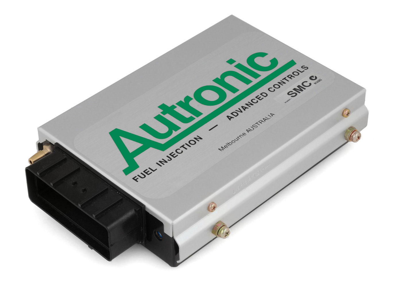
Autronic SMC is a standalone or earlier programmable engine-management system. Early SMC sequential engine management. Autronic distinguishes pre-1996 and later Rev C loom arrangements; its archive says early looms only suit pre-1996 ECUs. Model-specific information.
Identification and features
Record the ECU label, model, part number, hardware revision, firmware, configured injectors, ignition hardware and loom before comparing systems. Some outputs can be reassigned; hardware, software, current limits and engine-specific options determine what is actually available.
Wiring and pinout
Consult the Autronic SMC wiring and documentation source and identify the exact connector face, part and version. Do not apply wiring from a similarly named model. If an exact drawing is unavailable for the unit at hand, obtain it from the manufacturer or supplier before making connections.
Further information
J1 connector: manufacturer loom drawings
Transcribed from Autronic's Type 1 pre-1996 single-relay diagram, revision 003 and universal Type 2 Rev C single-relay diagram, revision 005. Both diagrams are linked from the manufacturer's SMC model page. The Type 1 loom is specified only for ECUs manufactured before 1996; the Type 2 drawing states it suits all SMC ECUs. The differences at pins 21 and 34 are preserved explicitly. Check the connector drawing, unit date, loom type, firmware and options before wiring.
J1 is drawn with pins 1, 13 and 25 at one end and 12, 24 and 36 at the opposite end. The optional diagnostic connection is shown dashed. “Not labelled” does not establish that a cavity is electrically unused. Colours apply to the depicted manufacturer looms; uncoloured ignition and diagnostic wiring is not specified in the drawings.
| J1 pin | Type 1 pre-1996 drawing | Type 2 Rev C universal drawing | Drawing wire colour |
|---|---|---|---|
| 1 | Injector 7 output | Injector 7 output | Grey/blue |
| 2 | Injector 6 output | Injector 6 output | Blue/black |
| 3 | Injector 4 output | Injector 4 output | Green/white |
| 4 | Injector 2 output | Injector 2 output | Orange/black |
| 5 | Injector 1 output | Injector 1 output | Pink/black |
| 6 | Coolant temperature input | Coolant temperature input | Pink |
| 7 | O2 input | O2 input | Blue |
| 8 | Reference trigger input | Reference trigger input | Green |
| 9 | Serial RX | Serial RX | Purple |
| 10 | Ignition 4 output | Ignition 4 output | Not specified |
| 11 | Ignition 2 output | Ignition 2 output | Not specified |
| 12 | Auxiliary output | Auxiliary output | Grey |
| 13 | ECU +12 V supply | ECU +12 V supply | Red |
| 14 | Injector 8 output | Injector 8 output | Blue/red |
| 15 | Injector 5 output | Injector 5 output | Green/yellow |
| 16 | Injector 3 output | Injector 3 output | Blue/white |
| 17 | Sensor ground | Sensor ground | Black |
| 18 | Throttle position input | Throttle position input | Orange |
| 19 | Throttle position supply | Throttle position supply | Red/white |
| 20 | Trigger supply | Trigger supply | Red/black |
| 21 | Serial I/O ground | Switch input | Black / green-orange respectively |
| 22 | Ignition 3 output | Ignition 3 output | Not specified |
| 23 | Diagnostic output (optional connection) | Diagnostic output (optional connection) | Not specified |
| 24 | Fuel pump output | Fuel pump output | Blue |
| 25 | +12 V / pump relay supply | +12 V / pump relay supply | Red |
| 26 | +12 V / auxiliary output supply | +12 V / auxiliary output supply | Pink/yellow |
| 27 | ECU ground | ECU ground | Black |
| 28 | ECU ground | ECU ground | Black |
| 29 | Ignition switch input | Ignition switch input | Red |
| 30 | Intake air temperature input | Intake air temperature input | White |
| 31 | Trigger ground | Trigger ground | Black |
| 32 | Cylinder pulse trigger input | Cylinder pulse trigger input | Yellow |
| 33 | Serial TX | Serial TX | Orange |
| 34 | Not labelled on Type 1 drawing | Serial I/O ground | Not specified / black respectively |
| 35 | Ignition 1 output | Ignition 1 output | Pink/white |
| 36 | Ignition output ground | Ignition output ground | Not specified |
Autronic’s drawings call for calibration mode flag 11 to be set to 1 for the illustrated relay arrangement. Check the source and the ECU’s actual configuration; the auxiliary and ignition output capabilities depend on the hardware and firmware fitted.