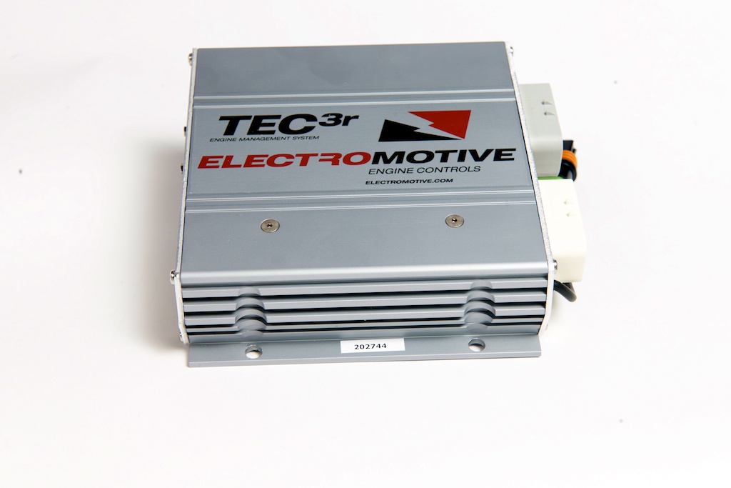
Electromotive TEC3r is a model in the Total Engine Control family. A later TEC3r model; its dedicated manual covers wiring, direct-fire units, coil firing and sequential fuel configurations. Manufacturer source.
Identification and software
Identify the exact model, serial, firmware and ignition-driver configuration before using a calibration or connecting a loom. WinTEC versions and hardware vary; the Electromotive manual archive separates the generations.
Wiring and pinout
Consult the model-specific manufacturer source and technical archive for the matching connector, firing order, ECU earths, injector drivers and ignition connections. Do not transfer TECgt200 or TECs200 positions to earlier TEC units. Where a complete exact-model pinout has not been verified, use the manufacturer documentation and verify the actual part number.
Availability
As of 17 November 2026, the manufacturer states it is not selling or repairing products. Electromotive notice. See the Electromotive family reference.
Hardware specification
Electromotive lists eight peak-and-hold injector drivers, sequential injection up to eight cylinders, staged injection with up to 16 injectors, and six high-current inductive coil drivers. The manufacturer page’s feature list mentions CAN output, while its specification table says CAN support is absent; verify the exact hardware and interface rather than assuming CAN capability. TEC3r product specification.
Manufacturer connector schedules
Electromotive's TEC3r manual, pages 22–23 and 123–125, documents the grey and white 23-way connectors and the separate two-way main ground. The manual cover is version 1.11; its connector appendices retain a 1.9.G footer. The TEC3r is different from TEC3 6/12: W16 and W17 are injector outputs here, and power connector position A is unused. Wire colours are manufacturer harness colours; a slash denotes the stripe. The G21 wire can be white/black on early harnesses. The manual specifies a combined maximum of 4 A for G1/G2/G20/G21 and separately for W18–W21.
TEC3r white 23-way connector
| Pin | Function | Harness wire |
|---|---|---|
| W1 | Coil channel A1 | White |
| W2 | Coil channel B1 | Red |
| W3 | Coil channel C1 | Black |
| W4 | Coil channel A2 | White |
| W5 | Coil channel B2 | Red |
| W6 | Coil channel C2 | Black |
| W7 | Injector channel 1 | Yellow/black |
| W8 | Injector channel 2 | Yellow/red |
| W9 | Injector channel 3 | Yellow/green |
| W10 | Coil wire shield | Bare |
| W11 | Idle air control D | Dark blue/white |
| W12 | Idle air control C | Dark blue/black |
| W13 | Idle air control B | Dark green/white |
| W14 | Idle air control A | Dark green/black |
| W15 | Injector channel 4 | Yellow/blue |
| W16 | Injector channel 7 | Light blue/green |
| W17 | Injector channel 8 | Light blue/blue |
| W18 | General-purpose output 1 | White/black |
| W19 | General-purpose output 2 | White/red |
| W20 | General-purpose output 3 | White/green |
| W21 | General-purpose output 4 | White/blue |
| W22 | Injector channel 5 | Light blue/black |
| W23 | Injector channel 6 | Light blue/red |
TEC3r grey 23-way connector
| Pin | Function | Harness wire |
|---|---|---|
| G1 | Tachometer output | Brown |
| G2 | Check-engine light | Pink |
| G3 | +5 V output | Grey/red |
| G4 | Crank/cam ground | Black |
| G5 | Switched +12 V input | Yellow |
| G6 | Oxygen sensor negative | Tan |
| G7 | Oxygen sensor positive | Violet |
| G8 | Knock sensor input | Orange |
| G9 | Crank sensor input | Red, shielded |
| G10 | Cam sensor input | Red, shielded |
| G11 | Crank/cam shield | Bare |
| G12 | Coolant temperature input | Grey |
| G13 | Manifold air temperature input | White |
| G14 | Throttle position input | Dark blue |
| G15 | MAP input | Dark green |
| G16 | General-purpose input 1 | Orange/black |
| G17 | General-purpose input 2 | Orange/red |
| G18 | General-purpose input 3 | Orange/green |
| G19 | General-purpose input 4 | Orange/blue |
| G20 | Fuel pump relay ground | Light green |
| G21 | Datalog status light ground | White/orange |
| G22 | Sensor ground | Black/white |
| G23 | One- or two-wire IAC output | Customer adds wire; diagram shows violet/white |
Two-way main ground connector
| Position | Function | Harness wire |
|---|---|---|
| A | Unused | — |
| B | Main battery negative | Black, 10 AWG |
Direct-fire-unit harness plugs
| Position | DFU 1 | DFU 2 |
|---|---|---|
| A | Coil A1 | Coil A2 |
| B | Coil B1 | Coil B2 |
| C | Coil C1 | Coil C2 |
| D | +12 V coil power | +12 V coil power |
DFU position D receives its separately fused +12 V supply from the power harness. The summary identifies injector 6 as W23, but the appendix harness diagram labels its breakout W4; W4 is separately listed as coil A2. The W23/W4 discrepancy needs manufacturer confirmation.
Power harness 070-40000 breakout wires
| Wire | Documented connection |
|---|---|
| Red, 10 AWG | Battery positive |
| Black, 16 AWG | Vehicle ground |
| Light green, 20 AWG | ECU G20 fuel-pump relay ground |
| Yellow, 20 AWG | ECU G5 switched +12 V input |
| Purple/white, 16 AWG | Injector power |
| Red/white | DFU power at position D |
| Green, 16 AWG | Fuel-pump and oxygen-sensor-heater positive |
| Yellow, 18 AWG | Ignition-switched +12 V request |
Serial communication connector
The AiM integration guide identifies these DB9 signal positions; other cavities are not specified in that guide.
DB9 communications
| Pin | Function |
|---|---|
| 2 | ECU RS-232 transmit |
| 3 | ECU RS-232 receive |
| 5 | Signal ground |