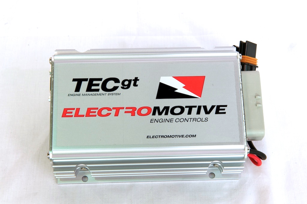
Electromotive TECgt is a model in the Total Engine Control family. TECgt engine-management ECU with a separate model-specific user guide. It is not identical by designation to TECgt200. Manufacturer source.
Identification and software
Identify the exact model, serial, firmware and ignition-driver configuration before using a calibration or connecting a loom. WinTEC versions and hardware vary; the Electromotive manual archive separates the generations.
Wiring and pinout
Consult the model-specific manufacturer source and technical archive for the matching connector, firing order, ECU earths, injector drivers and ignition connections. Do not transfer TECgt200 or TECs200 positions to earlier TEC units. Where a complete exact-model pinout has not been verified, use the manufacturer documentation and verify the actual part number.
Availability
As of 17 November 2026, the manufacturer states it is not selling or repairing products. Electromotive notice. See the Electromotive family reference.
Manufacturer connector schedule
The following TECgt grey connector schedule is from Electromotive's model-specific installation manual. Functions marked as alternatives depend on configuration; consult the manual for electrical ratings, connector view and harness details. Colours are those listed for the manufacturer's harness.
| Pin | Function | Harness colour |
|---|---|---|
| G1 | Coil channel C1 or A2 | Black |
| G2 | Coil channel B2 | Red |
| G3 | Injector channel 5 | Light blue/black |
| G4 | Injector channel 6 or GP I/O 7 | Light blue/red |
| G5 | Crank sensor input | Red |
| G6 | Sensor ground | Black/white |
| G7 | Crank/cam shield and crank sensor ground | Bare |
| G8 | +5 V output | Grey/red |
| G9 | GP I/O 8 | Orange/black |
| G10 | GP I/O 1 | White/black |
| G11 | Injector channel 2 | Yellow/red |
| G12 | Injector channel 1 | Yellow/black |
| G13 | DFU shield | Bare |
| G14 | IAC pin A or GP I/O 3 | Dark blue/black |
| G15 | IAC pin B or GP I/O 4 | Dark blue/white |
| G16 | Data log status light | White/orange |
| G17 | Fuel pump relay ground | Light green |
| G18 | Check engine light | Pink |
| G19 | Tachometer output | Brown |
| G20 | Speed sensor or GP I/O 2 | Orange/blue |
| G21 | MAT input | White |
| G22 | GP I/O 9 | Orange/red |
| G23 | Cam sensor input | Red |
| G24 | Coil channel B1 | Red |
| G25 | Coil channel A1 | White |
| G26 | IAC pin C or GP I/O 5 | Dark green/black |
| G27 | IAC pin D or GP I/O 6 | Dark green/white |
| G28 | CLT input | Grey |
| G29 | TPS input | Dark blue |
| G30 | MAP input | Dark green |
| G31 | Knock sensor input | Orange |
| G32 | Oxygen sensor − | Tan |
| G33 | Oxygen sensor + | Purple |
| G34 | Injector channel 3 | Yellow/green |
| G35 | Injector channel 4 | Yellow/blue |
Separate two-way power connector
| Pin | Function |
|---|---|
| A | Switched battery +12 V |
| B | Battery ground |