Removed text is struck through; added text is highlighted.
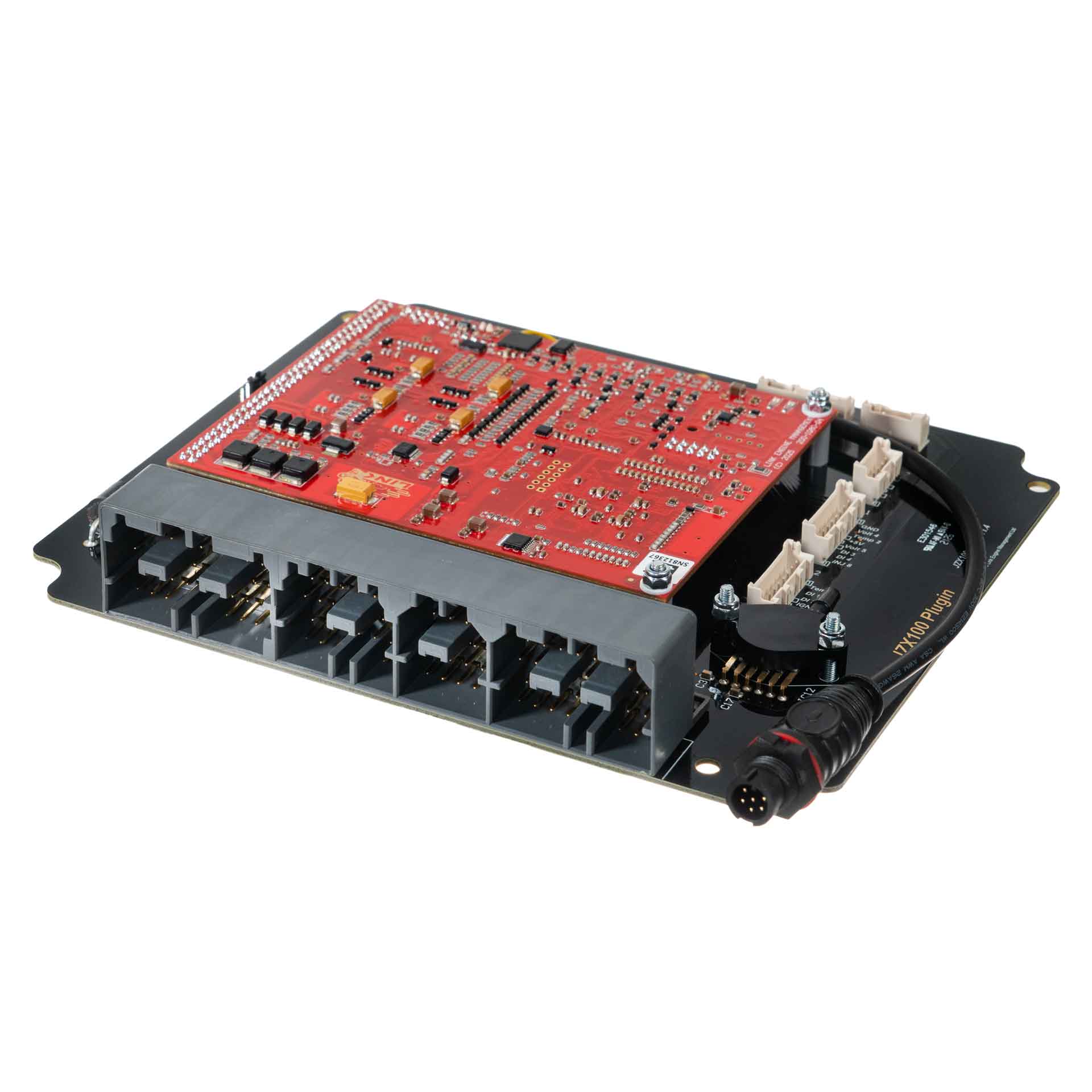
Manufacturer product image of JZX100X application ECU: Link ECU. Permission to republish confirmed by the user.
Link G4X JZX100X is a vehicle-specific programmable plug-in ECU for the Toyota JZX100 application listed in Link's model-specific manuals index. It is an application board rather than a universal wire-in ECU. Check the exact vehicle, market, engine, original ECU and board part number against the manufacturer's JZX100X installation manual.
Identification and installation
Record the Link model label and revision, donor factory ECU connector and car's engine and year. Plug-in boards connect to particular factory-harness layouts; the family or vehicle name alone does not establish every model-year or transmission combination. The manufacturer manual gives the supported application and any installation or configuration notes for this board.
G4X plug-in platforms offer configurable fuel and ignition control but available channels and features depend on the original header and board. The G4X plug-in general specifications are conditional on the particular application and do not mean every input is brought out to the factory harness.
Processor and hardwareLink's G4X plug-in specifications describe a 150 MHz "specialised engine management microprocessor" with 32-bit floating-point calculation, 12-bit ADC resolution, 4 Gb non-volatile flash, 512 MB of data logging and two CAN buses (vendor specification). The processor part number is not published by Link.Engine applicationLink's installation manual is written for the Toyota Mark II JZX100. The board drives six injectors and an inlet VVT solenoid (pins 11 and 12) and reads a VVT cam trigger on Trig 2 (pin 42), which matches the 1JZ-GTE VVT-i engine named for this ECU (part number 232-4000) in retailer listings (seen in search summary; not confirmed from Link's own page).
Pinout and tuning
The JZX100X installation manual is the model-specific source for board pinouts, expansion connections, electrical cautions and startup configuration. Use its connector orientation and the exact board version; do not copy a wire-in ECU pinout onto a factory harness. PCLink and manual downloads; Link manufacturer overview.
A structured, redrawn version of the schedules below, with the 100-pin main header face, is in Link G4X JZX100X connector pinout.
Manufacturer connector schedules
From Link's JZX100X installation manual. Link describes the pinout view as looking into the ECU from the wire side. A dash reproduces an unspecified source field; nc is Link's label. Confirm the vehicle, market and board revision before use.
The manufacturer labels main position 3 only “C88” without a cavity number; this is retained as published. Ignition 4–6 auxiliary channels are shared between the main and expansion headers. CAN 1 is not externally connected on this model; CAN 2 serves the vehicle temperature gauge and A/C system.
The guide labels this as JZX100 MAF information but names these additional Toyota applications. Confirm the actual sensor configuration; the manufacturer warns that at least two five-wire arrangements exist.
PinSymbolFunction1THAAir Temperature Sensor2E2Sensor Ground (Air Temperature Sensor)3EVGMass Airflow Sensor Ground4+BEFI Main Relay Switched Power5VGEngine Airflow
MAF sensor: JZS161 2JZGE after 07/2000 (Also JZS171 1JZGTE)
The guide labels this as JZX100 MAF information but names these additional Toyota applications. Confirm the actual sensor configuration; the manufacturer warns that at least two five-wire arrangements exist.
PinSymbolFunction1+BEFI Main Relay Switched Power2EVGMass Airflow Sensor Ground3VGEngine Airflow4THAAir Temperature Sensor5E2Sensor Ground (Air Temperature Sensor)
Open each version to inspect formatting, tables and photographs.
Revision 3: Link G4X JZX100X plug-in ECUManufacturer product image of JZX100X application ECU: Link ECU. Permission to republish confirmed by the user.
Link G4X JZX100X is a vehicle-specific programmable plug-in ECU for the Toyota JZX100 application listed in Link's model-specific manuals index. It is an application board rather than a universal wire-in ECU. Check the exact vehicle, market, engine, original ECU and board part number against the manufacturer's JZX100X installation manual.
Identification and installation
Record the Link model label and revision, donor factory ECU connector and car's engine and year. Plug-in boards connect to particular factory-harness layouts; the family or vehicle name alone does not establish every model-year or transmission combination. The manufacturer manual gives the supported application and any installation or configuration notes for this board.
G4X plug-in platforms offer configurable fuel and ignition control but available channels and features depend on the original header and board. The G4X plug-in general specifications are conditional on the particular application and do not mean every input is brought out to the factory harness.
Pinout and tuning
The JZX100X installation manual is the model-specific source for board pinouts, expansion connections, electrical cautions and startup configuration. Use its connector orientation and the exact board version; do not copy a wire-in ECU pinout onto a factory harness. PCLink and manual downloads; Link manufacturer overview.
Manufacturer connector schedules
From Link's JZX100X installation manual. Link describes the pinout view as looking into the ECU from the wire side. A dash reproduces an unspecified source field; nc is Link's label. Confirm the vehicle, market and board revision before use.
The manufacturer labels main position 3 only “C88” without a cavity number; this is retained as published. Ignition 4–6 auxiliary channels are shared between the main and expansion headers. CAN 1 is not externally connected on this model; CAN 2 serves the vehicle temperature gauge and A/C system.
The guide labels this as JZX100 MAF information but names these additional Toyota applications. Confirm the actual sensor configuration; the manufacturer warns that at least two five-wire arrangements exist.
Pin
Symbol
Function
1
THA
Air Temperature Sensor
2
E2
Sensor Ground (Air Temperature Sensor)
3
EVG
Mass Airflow Sensor Ground
4
+B
EFI Main Relay Switched Power
5
VG
Engine Airflow
MAF sensor: JZS161 2JZGE after 07/2000 (Also JZS171 1JZGTE)
The guide labels this as JZX100 MAF information but names these additional Toyota applications. Confirm the actual sensor configuration; the manufacturer warns that at least two five-wire arrangements exist.
Pin
Symbol
Function
1
+B
EFI Main Relay Switched Power
2
EVG
Mass Airflow Sensor Ground
3
VG
Engine Airflow
4
THA
Air Temperature Sensor
5
E2
Sensor Ground (Air Temperature Sensor)
RS232 connector
Pin
Function
Wire colour
1
Comms GND
Brown
2
nc
Green
3
nc
White
4
RS232-RX
Grey
5
RS232-TX
Yellow
Revision 4: Link G4X JZX100X plug-in ECUManufacturer product image of JZX100X application ECU: Link ECU. Permission to republish confirmed by the user.
Link G4X JZX100X is a vehicle-specific programmable plug-in ECU for the Toyota JZX100 application listed in Link's model-specific manuals index. It is an application board rather than a universal wire-in ECU. Check the exact vehicle, market, engine, original ECU and board part number against the manufacturer's JZX100X installation manual.
Identification and installation
Record the Link model label and revision, donor factory ECU connector and car's engine and year. Plug-in boards connect to particular factory-harness layouts; the family or vehicle name alone does not establish every model-year or transmission combination. The manufacturer manual gives the supported application and any installation or configuration notes for this board.
G4X plug-in platforms offer configurable fuel and ignition control but available channels and features depend on the original header and board. The G4X plug-in general specifications are conditional on the particular application and do not mean every input is brought out to the factory harness.
Processor and hardware
Link's G4X plug-in specifications describe a 150 MHz "specialised engine management microprocessor" with 32-bit floating-point calculation, 12-bit ADC resolution, 4 Gb non-volatile flash, 512 MB of data logging and two CAN buses (vendor specification). The processor part number is not published by Link.
Engine application
Link's installation manual is written for the Toyota Mark II JZX100. The board drives six injectors and an inlet VVT solenoid (pins 11 and 12) and reads a VVT cam trigger on Trig 2 (pin 42), which matches the 1JZ-GTE VVT-i engine named for this ECU (part number 232-4000) in retailer listings (seen in search summary; not confirmed from Link's own page).
Pinout and tuning
The JZX100X installation manual is the model-specific source for board pinouts, expansion connections, electrical cautions and startup configuration. Use its connector orientation and the exact board version; do not copy a wire-in ECU pinout onto a factory harness. PCLink and manual downloads; Link manufacturer overview.
From Link's JZX100X installation manual. Link describes the pinout view as looking into the ECU from the wire side. A dash reproduces an unspecified source field; nc is Link's label. Confirm the vehicle, market and board revision before use.
The manufacturer labels main position 3 only “C88” without a cavity number; this is retained as published. Ignition 4–6 auxiliary channels are shared between the main and expansion headers. CAN 1 is not externally connected on this model; CAN 2 serves the vehicle temperature gauge and A/C system.
The guide labels this as JZX100 MAF information but names these additional Toyota applications. Confirm the actual sensor configuration; the manufacturer warns that at least two five-wire arrangements exist.
Pin
Symbol
Function
1
THA
Air Temperature Sensor
2
E2
Sensor Ground (Air Temperature Sensor)
3
EVG
Mass Airflow Sensor Ground
4
+B
EFI Main Relay Switched Power
5
VG
Engine Airflow
MAF sensor: JZS161 2JZGE after 07/2000 (Also JZS171 1JZGTE)
The guide labels this as JZX100 MAF information but names these additional Toyota applications. Confirm the actual sensor configuration; the manufacturer warns that at least two five-wire arrangements exist.