Removed text is struck through; added text is highlighted.
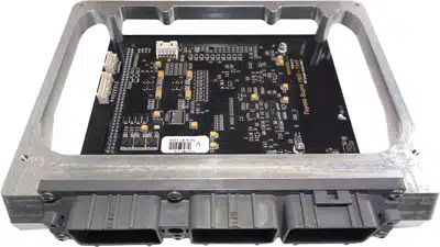
Vi-PEC iSupra i-Series plug-in ECU shown as a family illustration; this V-Series model's board, enclosure and vehicle connectors differ. Image: Link Engine Management Vi-PEC product archive, reproduced with permission.
Vi-PEC V Series Toyota ST205 is a V Series plug-in ECU documented for Toyota MR2 and Celica ST205 applications as listed by Link. It is a vehicle-specific replacement board, and the precise model year, engine, ECU connector and market variant must be checked against the installation guide. Link's Vi-PEC manual index.
Installation and pin functions
Use the specific Vi-PEC installation manual for this application. Its installation instructions and pin-function sections identify connections and application differences; a similarly named V Series plug-in board for another vehicle must not be used as a wiring reference. Check the original ECU part number and wiring before fitting.
Programming and support
Link lists Vi-PEC Tuning Software (VTS) for the V Series. Firmware compatibility and the calibration depend on the ECU version. Consult the software archive and retain the original calibration before any change.
Identification limits
This page is indexed by the documented application rather than an independently verified manufacturer SKU. Check the manual for exact compatibility and do not infer additional vehicle fitments.
Manufacturer pinout tables
All positions listed in the application-specific Vi-PEC installation guide, page 20, appear below. The guide specifies the view looking into the ECU from the wire side. It does not list every factory connector cavity; omitted positions are not assumed unused. The guide lists this schedule for Celica ST205 and MR2 Rev2–3. On V1.0 boards An Volt 4 is shared by pin 34 and expansion position 4: connect only one sensor to that shared channel.
Open each version to inspect formatting, tables and photographs.
Revision 3: Vi-PEC V Series Toyota ST205Vi-PEC iSupra i-Series plug-in ECU shown as a family illustration; this V-Series model's board, enclosure and vehicle connectors differ. Image: Link Engine Management Vi-PEC product archive, reproduced with permission.
Vi-PEC V Series Toyota ST205 is a V Series plug-in ECU documented for Toyota MR2 and Celica ST205 applications as listed by Link. It is a vehicle-specific replacement board, and the precise model year, engine, ECU connector and market variant must be checked against the installation guide. Link's Vi-PEC manual index.
Installation and pin functions
Use the specific Vi-PEC installation manual for this application. Its installation instructions and pin-function sections identify connections and application differences; a similarly named V Series plug-in board for another vehicle must not be used as a wiring reference. Check the original ECU part number and wiring before fitting.
Programming and support
Link lists Vi-PEC Tuning Software (VTS) for the V Series. Firmware compatibility and the calibration depend on the ECU version. Consult the software archive and retain the original calibration before any change.
Identification limits
This page is indexed by the documented application rather than an independently verified manufacturer SKU. Check the manual for exact compatibility and do not infer additional vehicle fitments.
Manufacturer pinout tables
All positions listed in the application-specific Vi-PEC installation guide, page 20, appear below. The guide specifies the view looking into the ECU from the wire side. It does not list every factory connector cavity; omitted positions are not assumed unused. The guide lists this schedule for Celica ST205 and MR2 Rev2–3. On V1.0 boards An Volt 4 is shared by pin 34 and expansion position 4: connect only one sensor to that shared channel.
Main ECU connector: documented positions
Position
ECU function
2
Injection 1
51
DI1
3
Injection 2
52
DI2
4
Aux 2
53
DI3
5
Aux 1
57
Aux5
6
Aux - Inj6
63
Aux6
7
Aux - Ign2
70
Aux7
8
Aux - Ign3
71
+14V
10
Trig1
46
Ground
12
Aux3
34
AnVolt4*
13
Aux8
15
Injection 3
16
Injection 4
17
Aux - Ign4
18
Aux - Ign5
20
Ignition 1
22
Trig2
33
AnVolt1
35
AnTemp1
36
AnTemp2
37
Anvolt3
38
+5V
39
Aux4
44
AnVolt2
45
AnTemp3
Other connections
Position
ECU function
Expansion 1
DI4
Expansion 2
DI5
Expansion 3
DI6
Expansion 4
AnVolt4*
Expansion 5
AnVolt5
Expansion 6
AnVolt6
Revision 3: Vi-PEC V Series Toyota ST205Vi-PEC iSupra i-Series plug-in ECU shown as a family illustration; this V-Series model's board, enclosure and vehicle connectors differ. Image: Link Engine Management Vi-PEC product archive, reproduced with permission.
Vi-PEC V Series Toyota ST205 is a V Series plug-in ECU documented for Toyota MR2 and Celica ST205 applications as listed by Link. It is a vehicle-specific replacement board, and the precise model year, engine, ECU connector and market variant must be checked against the installation guide. Link's Vi-PEC manual index.
Installation and pin functions
Use the specific Vi-PEC installation manual for this application. Its installation instructions and pin-function sections identify connections and application differences; a similarly named V Series plug-in board for another vehicle must not be used as a wiring reference. Check the original ECU part number and wiring before fitting.
Programming and support
Link lists Vi-PEC Tuning Software (VTS) for the V Series. Firmware compatibility and the calibration depend on the ECU version. Consult the software archive and retain the original calibration before any change.
Identification limits
This page is indexed by the documented application rather than an independently verified manufacturer SKU. Check the manual for exact compatibility and do not infer additional vehicle fitments.
Manufacturer pinout tables
All positions listed in the application-specific Vi-PEC installation guide, page 20, appear below. The guide specifies the view looking into the ECU from the wire side. It does not list every factory connector cavity; omitted positions are not assumed unused. The guide lists this schedule for Celica ST205 and MR2 Rev2–3. On V1.0 boards An Volt 4 is shared by pin 34 and expansion position 4: connect only one sensor to that shared channel.