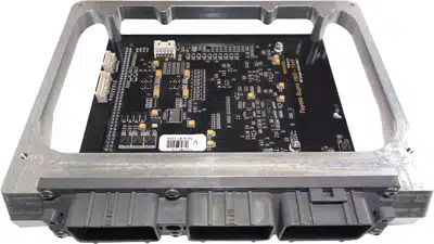
Vi-PEC V Series Nissan 300ZX is a V Series plug-in ECU documented for Nissan 300ZX Z32. It is a vehicle-specific replacement board, and the precise model year, engine, ECU connector and market variant must be checked against the installation guide. Link's Vi-PEC manual index.
Installation and pin functions
Use the specific Vi-PEC installation manual for this application. Its installation instructions and pin-function sections identify connections and application differences; a similarly named V Series plug-in board for another vehicle must not be used as a wiring reference. Check the original ECU part number and wiring before fitting.
Programming and support
Link lists Vi-PEC Tuning Software (VTS) for the V Series. Firmware compatibility and the calibration depend on the ECU version. Consult the software archive and retain the original calibration before any change.
Identification limits
This page is indexed by the documented application rather than an independently verified manufacturer SKU. Check the manual for exact compatibility and do not infer additional vehicle fitments.
Manufacturer pinout tables
All positions listed in the application-specific Vi-PEC installation guide, page 20, appear below. The guide specifies the view looking into the ECU from the wire side. It does not list all factory connector cavities; omitted positions are not assumed unused. The guide identifies the Nissan 300ZX Z32. It lists Aux–Inj 8 at both pins 6 and 19; verify the loom and configured output.
Main ECU connector: documented positions
| Position | ECU function |
|---|---|
| 101 | Injector 1 |
| 29 | An Volt 6 |
| 103 | Injector 3 |
| 32 | Aux 7 |
| 104 | Aux 2 |
| 34 | An Volt 5 |
| 105 | Injector 5 |
| 35 | Aux 5 |
| 110 | Injector 2 |
| 36 | An Temp 2 |
| 112 | Injector 4 |
| 38 | An Volt 3 |
| 113 | Aux 8 |
| 41 | Trig 2 |
| 114 | Injector 6 |
| 42 | Trig 1 |
| 116 | Ground |
| 43 | DI 2 |
| 44 | DI 4 |
| 1 | Ignition 1 |
| 45 | +12V Key On |
| 2 | Ignition 2 |
| 46 | DI 1 |
| 3 | Ignition 3 |
| 48 & 57 | + 5V Out |
| 4 | Aux – Inj 7 |
| 49 & 59 | +14V |
| 6 | Aux – Inj 8 |
| 53 | DI 3 |
| 7 | Aux 4 |
| 55 | An Volt 4 |
| 9 | Aux 3 |
| 11 | Ignition 4 |
| 12 | Ignition 5 |
| 13 | Ignition 6 |
| 18 | Aux 6 |
| 19 | Aux - Inj 8 |
| 23 | Knock 1 |
| 25 | Aux 1 |
| 27 | An Volt 2 |
| 28 | An Temp 1 |
Other connections
| Position | ECU function |
|---|---|
| Internal MAP | An Volt 1 |
| Expansion 1 | Signal Ground |
| Expansion 2 | +5V Out |
| Expansion 3 | DI 5 |
| Expansion 4 | DI 6 |
| Expansion 5 | An Volt 8 |
| Expansion 6 | An Volt 7 |
| Expansion 7 | An Temp 3 |
| Expansion 8 | An Temp 4 |