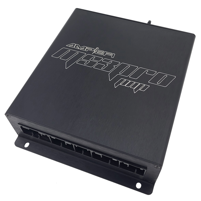
MSPNP-Pro MM9093 is a vehicle-specific MS3Pro-based plug-in engine management ECU. The manufacturer’s model-specific installation guide lists the following application: 1990–1993 Mazda Miata 1.6L with manual transmission. Fitment depends on the original ECU connector, engine, harness and market; confirm the exact part number before installation.
Application and installation
The guide directs removal of the ST SIGN fuse before running the ECU. Sequential injection requires wiring changes on 1990–1992 and 1993 federal cars; it identifies 1993 California cars separately. Read its instructions and diagrams. Plug-in does not mean every optional feature is prewired: follow the relevant guide for setup, sensors, jumpers, base tune and ignition-timing checks.
Pinout and documentation
AMP EFI MM9093 vehicle-specific installation and connector documentation is the primary source for this model. Check the connector orientation, version and any configurable or optional functions before wiring. Diagrams may be shown as images in the guide; this page does not substitute a pin assignment from another MSPNP model.
See the manufacturer’s ECU documentation index and firmware and base-tune index. Initial maps require verification and tuning for the particular engine.
Rear options connector — A–Z
From this model's AMP EFI installation guide. These are rear options connections; they do not constitute the full original vehicle ECU connector pinout. Check the manufacturer's connector orientation and configuration before wiring; functions marked as defaults are configurable.
| Pin | Function | Default or note in source |
|---|---|---|
| A | Sensor ground | — |
| B | Knock sensor | — |
| C | Analog input 2 | — |
| D | Analog input 1 | MAF |
| E | IAT | — |
| F | External MAP sensor | — |
| G | CANL | — |
| H | +5 V reference | — |
| I | CANH | — |
| J | +12 V ignition | Maximum 0.5 A |
| K | Digital frequency in 3 | — |
| L | Digital frequency in 2 | VSS |
| M | Digital in 1 | Flex |
| N | Digital in 2 | Clutch signal |
| O | Digital in 12 V (DI4) | — |
| P | High current 1 | VVT |
| Q | High current 3 | Nitrous |
| R | High current 2 | Boost control |
| S | Ignition D logic level | — |
| T | Injector H | High Z or GPIO only |
| U | Ignition C logic level | — |
| V | Injector G | High Z or GPIO only |
| W | Ignition B logic level | — |
| X | Injector F | High Z or GPIO only |
| Y | Ignition A logic level | — |
| Z | Injector E | High Z or GPIO only |
Vehicle and optional connector assignments
Transcribed from this model's AMP EFI guide. Connector 1 and 4 are labelled factory wiring; connector 2 is optional wiring, and connector 3 is labelled optional wiring. “N/C” reproduces the guide's label, not an independent check of every vehicle harness; check the original diagram, connector orientation, jumpers and exact vehicle.
Connector 1
| Pin | Function from guide |
|---|---|
| 1A | N/C |
| 1B | +12 V ignition |
| 1C | Fuel pump relay (12 V) |
| 1D | N/C |
| 1E | CEL (via DFIN1) |
| 1F | Tach out |
| 1G | Cylinder 1/4 ignition coil (Ignition A out) |
| 1H | Cylinder 2/3 ignition coil (Ignition B out) |
| 1I | N/C |
| 1J | A/C relay (Injector J out) |
| 1K | N/C |
| 1L | Fan 1 relay (PWM2) |
| 1M | VSS (DFIN2) |
| 1N | Throttle switch 5 V |
| 1O | N/C |
| 1P | N/C |
| 1Q | A/C switch in |
| 1R | Fan 1 relay (PWM2 via J6) |
| 1S | N/C |
| 1T | N/C |
| 1U | N/C |
| 1V | Clutch switch (digital in 2) |
Connector 2
| Pin | Function from guide |
|---|---|
| 2A | CANH |
| 2B | Oxygen sensor |
| 2C | CANL |
| 2D | Tach out |
| 2E | External MAP sensor |
| 2F | Knock sensor |
| 2G | Ground |
| 2H | Digital in 1 (flex) |
| 2I | PWM3 |
| 2J | Digital in 12 V (DI4) |
| 2K | Analog in 2 |
| 2L | High current 2 (boost) |
Connector 3
| Pin | Function from guide |
|---|---|
| 3A | Ignition C (cylinder 4 sequential) |
| 3B | Ignition D (cylinder 2 sequential) |
| 3C | Ignition A (cylinders 1/4 wasted spark, cylinder 1 sequential) |
| 3D | Ignition B (cylinders 2/3 wasted spark, cylinder 3 sequential) |
| 3E | Injector C (cylinder 4 sequential) |
| 3F | Injector D (cylinder 2 sequential) |
| 3G | Injector A (cylinders 1/4 batch, cylinder 1 sequential) |
| 3H | Injector B (cylinders 2/3 batch, cylinder 3 sequential) |
| 3I | +12 V out (relay supply) |
| 3J | High current 1 (VVT) |
| 3K | Sensor ground |
| 3L | IAC |
| 3M | CKP (crank) signal |
| 3N | +5 Vref |
| 3O | CMP (cam) signal |
| 3P | TPS |
Connector 4
| Pin | Function from guide |
|---|---|
| 4A | Ground |
| 4B | Ground |
| 4C | Sensor ground |
| 4D | Sensor ground |
| 4E | CKP (crank) signal |
| 4F | Sensor ground |
| 4G | CMP (cam) signal |
| 4H | N/C |
| 4I | N/C |
| 4J | N/C |
| 4K | +5 Vref |
| 4L | TPS |
| 4M | N/C |
| 4N | O2 sensor |
| 4O | VAM output (external MAP) |
| 4P | IAT sensor |
| 4Q | CLT sensor |
| 4R | N/C |
| 4S | Condenser fan (Injector I out) |
| 4T | Fuel pump relay (unused on 1990–1993) |
| 4U | Injector A |
| 4V | Injector B (Injector D — 1993 California emissions) |
| 4W | IAC (PWM1) |
| 4X | N/C |
| 4Y | N/C (Injector B — 1993 California emissions) |
| 4Z | N/C (Injector C — 1993 California emissions) |