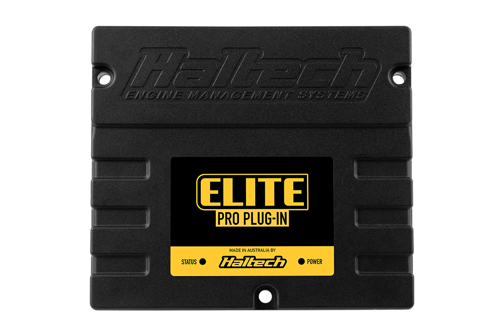
Haltech's downloads page lists Elite Falcon as a distinct ESP ECU firmware family. A Haltech product notice separately refers to an Elite Falcon Pro Plug-in; the relationship of every Elite Falcon firmware package and product variation has not been established in this reference. Haltech firmware index; Elite range notice.
Identification and wiring
Record the full label, ECU part number, serial, firmware and factory connector; verify the exact Falcon application with Haltech. A complete pinout, applicable vehicle range and specifications were not verified for the firmware family as a whole. Do not use a different Elite model's pin assignments by assumption. Search the manufacturer's guides and downloads for the actual part number.
See Haltech ECU index.
Auxiliary connector: manufacturer diagram
Haltech's Elite PRO Ford Falcon I6 Barra quick-start guide illustrates this 34-position auxiliary connector and the optional LSU 4.9 harness. Positions 18–23 below are shown as the corresponding sensor connector cavities in the guide, not inferred electrical function names. Confirm connector view and the actual loom before wiring. CAN polarity is not separately labelled on the illustrated diagram. The factory vehicle connector is not covered by this auxiliary table.
| Auxiliary pin | Documented connection |
|---|---|
| 1 | CAN connection (white; confirm CAN polarity against the harness) |
| 2 | CAN connection (blue; confirm CAN polarity against the harness) |
| 3 | +12 V sensor / relay supply |
| 4 | Signal ground |
| 5 | Digital pulsed input 1 |
| 6 | Digital pulsed input 2 |
| 7 | Digital pulsed input 3 |
| 8 | Digital pulsed input 4 |
| 9 | +5 V sensor supply |
| 10 | Injector 1 / DPO 1 |
| 11 | Injector 2 / DPO 2 |
| 12 | Injector 3 / DPO 3 |
| 13 | Injector 4 / DPO 4 |
| 14 | Injector 5 / DPO 5 |
| 15 | Injector 6 / DPO 6 |
| 16 | Injector 7 / DPO 7 |
| 17 | Injector 8 / DPO 8 |
| 18 | Wideband LSU 4.9 sensor cavity 4 (grey) |
| 19 | Wideband LSU 4.9 sensor cavity 2 (yellow) |
| 20 | Wideband LSU 4.9 sensor cavity 1 (red) |
| 21 | Wideband LSU 4.9 sensor cavity 6 (black) |
| 22 | Wideband LSU 4.9 sensor cavity 3 (white) |
| 23 | Wideband LSU 4.9 sensor cavity 5 (green) |
| 24 | Analog voltage input 1 |
| 25 | Analog voltage input 2 |
| 26 | Not used in the shown harness |
| 27 | Not used in the shown harness |
| 28 | Not used in the shown harness |
| 29 | Not used in the shown harness |
| 30 | Not used in the shown harness |
| 31 | Not used in the shown harness |
| 32 | Analog voltage input 3 |
| 33 | Analog voltage input 4 |
| 34 | Signal ground |
The guide describes the injector channels as usable for staged injection or digital pulsed outputs; consult it for configuration and current limits. “Not used” describes the illustrated harness only.