Removed text is struck through; added text is highlighted.
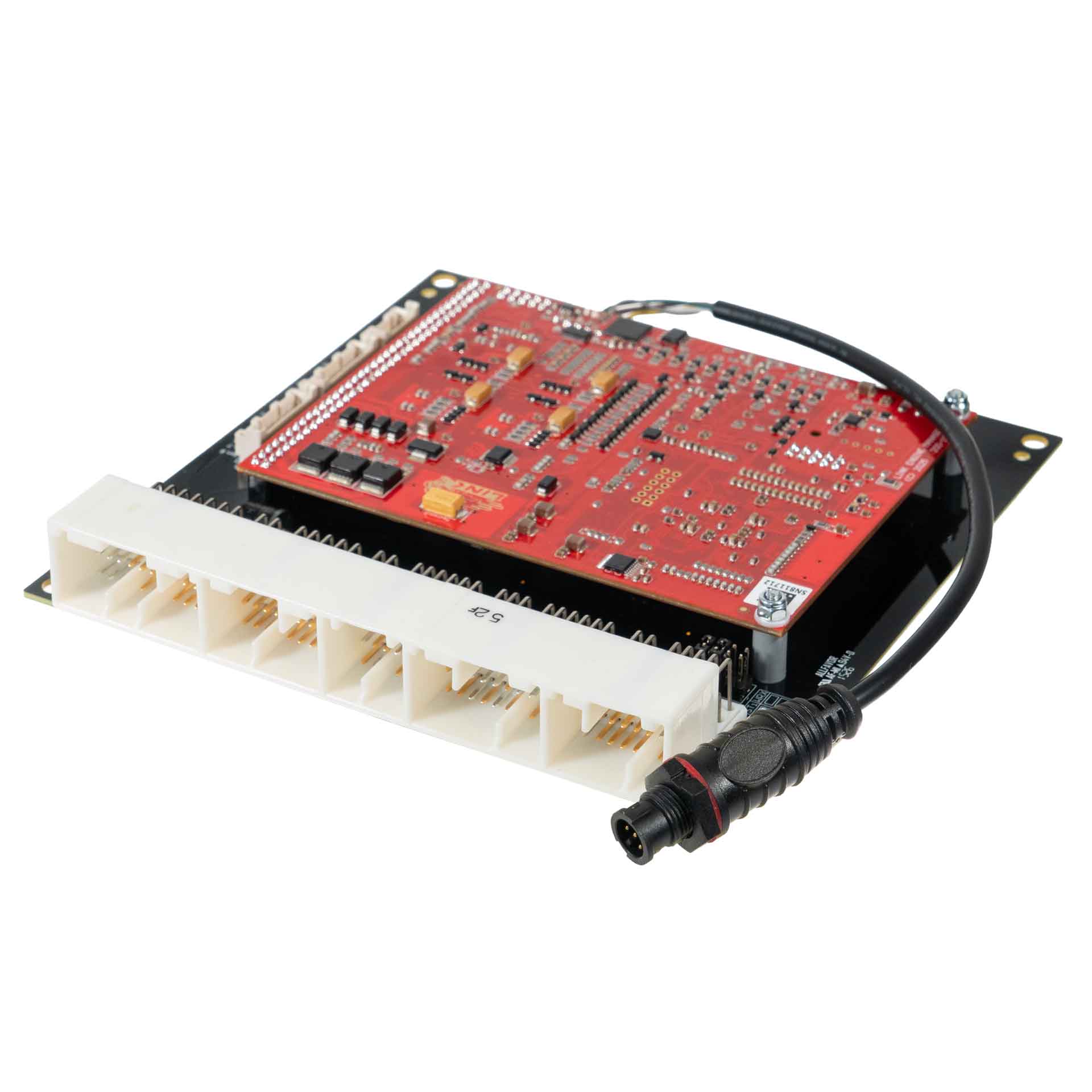
Manufacturer product image of WRX9X application ECU: Link ECU. Permission to republish confirmed by the user.
Link G4X WRX9X is a vehicle-specific programmable plug-in ECU for the Subaru WRX version 7–9 application listed in Link's model-specific manuals index. It is an application board, rather than the universal wire-in ECU. Check the exact vehicle, market, engine, original ECU and board part number against the manufacturer's WRX9X installation manual.
Identification and installation
Record the Link model label and revision, donor factory ECU connector and car's engine and year. Plug-in boards connect to particular factory-harness layouts; the family or vehicle name alone does not establish every model-year or transmission combination. The manufacturer manual gives the supported application and any installation or configuration notes for this board.
G4X plug-in platforms offer configurable fuel and ignition control but available channels and features depend on the original header and board. The G4X plug-in general specifications are conditional on the particular application and do not mean every input is brought out to the factory harness.
Pinout and tuning
The WRX9X installation manual is the model-specific source for board pinouts, expansion connections, electrical cautions and startup configuration. Use its connector orientation and the exact board version; do not copy a wire-in ECU pinout onto a factory harness. PCLink and manual downloads; Link manufacturer overview.
ProcessorLink does not name the microcontroller. Its G4X plug-in specification describes a 150 MHz specialised engine-management microprocessor with 32-bit floating-point calculation, 12-bit ADC resolution and 4 Gb of non-volatile flash (manufacturer specification).Engine applicationsThe board is for the GD/GG-chassis Subaru Impreza WRX and STi, version 7 to 9, with the EJ20 turbocharged engine (EJ205 in the WRX, EJ207 in the Japanese-market STi). Dealer listings give model years from 2000 or 2001 to 2007, with ranges that vary by seller, and manual transmission only (dealer listings, not manufacturer documentation). The Link manual covers both WRX and STi wiring, selected by jumpers on the bottom board.Connector pinoutAll 122 factory header positions and the Link expansion and CAN/RS232 connectors are drawn and indexed in the Link G4X WRX9X connector pinout.
Manufacturer connector schedules
From Link's WRX9X installation manual (2025). Link states that its pinouts are viewed looking into the ECU from the wire side. A dash reproduces an unspecified source field; nc is Link's label. Applies to the V7–9 WRX/STi layouts documented by Link. On some Australian-market vehicles pin D11 controls the alternator instead of intercooler spray; the spray is controlled separately and pin B12 is not connected. Configure the sample map for the actual vehicle.
Factory main header positions
Factory pinLink ECU channelFactory functionA-1DI 5Vehicle SpeedC-21Ignition 4IgnitionA-2Main Relay (WRX) / DI 3 (STI)Main Relay Control (WRX) / A/C Request (STI)C-22Ignition 3IgnitionA-3DI 10Rear de-mist switchC-23Ignition 2IgnitionA-4nc—C-24Ignition 1IgnitionA-5Ignition Switch (STI)Controls Main RelayA-6DI 3 (WRX) / Main Relay (STI)A/C Request (WRX) / Main Relay Control (STI)D-1Injector 1InjectionA-7Ground—D-2+14V Main RelayECU PowerA-8nc—D-3+14V Main RelayECU PowerA-9nc—D-4nc—A-10nc—D-5nc—A-11nc—D-6nc—A-12nc—D-7nc—A-13nc—D-8Ground—A-14Ignition Switch (WRX)Controls Main RelayD-9Ground—A-15Ground—D-10nc—A-16DI 6Start SignalD-11Injector 6 (Aux)IC Spray Relay*A-17nc—D-12nc—A-18nc—D-13nc—A-19nc—D-14An Temp 3IAT (Spec C)A-20nc—D-15Aux 5CE LightA-21nc—D-16nc—A-22Ground—D-17Injector 5 (Aux)Engine FanD-18Ground (O2 Shield)—B-1Trig 2Trig 2D-19nc—B-2Trig 1Trig 1D-20nc—B-3nc—D-21nc—B-4Knock 1KnockD-22nc—B-5nc—D-23nc—B-6nc—D-24Aux 6Boost SolenoidB-7An Volt 3TPS (Main)D-25nc—B-8An Volt 1MAP SensorD-26nc—B-9+5V Out—D-27Injector 7 (Aux)A/C Clutch RelayB-10Ground (Trig 2)—D-28Injector 8 (Aux)A/C Fan RelayB-11Ground (Trig 1)—D-29nc—B-12DI 4IC Spray SwitchD-30nc—B-13nc—D-31nc—B-14nc—B-15nc—E-1Ground—B-16nc—E-2DI 2Bank 1 Inl Cam PosB-17An Volt 4Rear O2 SignalE-3Ground (Cam Pos)—B-18An Temp 2ECTE-4+14V Out (TGV)—B-19Ground (Signal)—E-5Ground (TGV)—B-20nc—E-6+14V Out (Cam)—B-21Ground (Shield)—E-7Ground (AFM)—B-22Ground (Shield)—E-8Ground (AFM Shield)—B-23nc—E-9DI 1Bank 2 Inl Cam PosB-24An Volt 5Power Steer SwitchE-10+14V Out (TGV)—B-25nc—E-11Ground (TGV)—B-26Ground (Shield)—E-12Aux 2Bank 1 Inl AVCS SolB-27An Temp 1IAT (AFM)E-13An Volt 2AFM SignalB-28nc—E-14Ground (Cam Shield)—E-15Ground (Cam Pos)—C-1nc—E-16Aux 1Bank 2 Inl AVCS SolC-2nc—E-17+14V Out (Cam)—C-3nc—C-4Injector 4InjectionC-5Injector 3InjectionC-6Injector 2InjectionC-7nc—C-8Ground—C-9Ignition 5 (Aux)TachoC-10Aux 3ISC SolenoidC-11nc—C-12nc—C-13Aux 8Rear O2 HeaterC-14nc—C-15Aux 7FP Speed ControlC-16Aux 7FP Speed ControlC-17Ground—C-18Ground—C-19nc—C-20nc—
Expansion connector
PinLink ECU channelFactory function1Ignition 6 (Aux)—2Ignition 7 (Aux)—3Ignition 8 (Aux)—4DI 7—5DI 8—6DI 9—7An temp 4—8An Volt 11—9Ground (Signal)—10+5V Out—11Aux 9—12Aux 10—13An Volt 6—14An Volt 7—15An Volt 9—16An Volt 10—
SourcesLink Engine Management: WRXLink (7-9) plug-in ECU installation manual, manufacturer documentation, 2025. Accessed 19 November 2026.Link Engine Management: G4X plug-in ECU specifications, manufacturer specification sheet. Accessed 19 November 2026.Fastlane Spares, Link WRXLink 7-9 WRX9X, and Speeding, Subaru WRX/STi V7-9 Link plug-in ECU, dealer listings. Seen in search summary, 19 November 2026.
Rendered revisions
Open each version to inspect formatting, tables and photographs.
Revision 3: Link G4X WRX9X plug-in ECUManufacturer product image of WRX9X application ECU: Link ECU. Permission to republish confirmed by the user.
Link G4X WRX9X is a vehicle-specific programmable plug-in ECU for the Subaru WRX version 7–9 application listed in Link's model-specific manuals index. It is an application board, rather than the universal wire-in ECU. Check the exact vehicle, market, engine, original ECU and board part number against the manufacturer's WRX9X installation manual.
Identification and installation
Record the Link model label and revision, donor factory ECU connector and car's engine and year. Plug-in boards connect to particular factory-harness layouts; the family or vehicle name alone does not establish every model-year or transmission combination. The manufacturer manual gives the supported application and any installation or configuration notes for this board.
G4X plug-in platforms offer configurable fuel and ignition control but available channels and features depend on the original header and board. The G4X plug-in general specifications are conditional on the particular application and do not mean every input is brought out to the factory harness.
Pinout and tuning
The WRX9X installation manual is the model-specific source for board pinouts, expansion connections, electrical cautions and startup configuration. Use its connector orientation and the exact board version; do not copy a wire-in ECU pinout onto a factory harness. PCLink and manual downloads; Link manufacturer overview.
Manufacturer connector schedules
From Link's WRX9X installation manual (2025). Link states that its pinouts are viewed looking into the ECU from the wire side. A dash reproduces an unspecified source field; nc is Link's label. Applies to the V7–9 WRX/STi layouts documented by Link. On some Australian-market vehicles pin D11 controls the alternator instead of intercooler spray; the spray is controlled separately and pin B12 is not connected. Configure the sample map for the actual vehicle.
Factory main header positions
Factory pin
Link ECU channel
Factory function
A-1
DI 5
Vehicle Speed
C-21
Ignition 4
Ignition
A-2
Main Relay (WRX) / DI 3 (STI)
Main Relay Control (WRX) / A/C Request (STI)
C-22
Ignition 3
Ignition
A-3
DI 10
Rear de-mist switch
C-23
Ignition 2
Ignition
A-4
nc
—
C-24
Ignition 1
Ignition
A-5
Ignition Switch (STI)
Controls Main Relay
A-6
DI 3 (WRX) / Main Relay (STI)
A/C Request (WRX) / Main Relay Control (STI)
D-1
Injector 1
Injection
A-7
Ground
—
D-2
+14V Main Relay
ECU Power
A-8
nc
—
D-3
+14V Main Relay
ECU Power
A-9
nc
—
D-4
nc
—
A-10
nc
—
D-5
nc
—
A-11
nc
—
D-6
nc
—
A-12
nc
—
D-7
nc
—
A-13
nc
—
D-8
Ground
—
A-14
Ignition Switch (WRX)
Controls Main Relay
D-9
Ground
—
A-15
Ground
—
D-10
nc
—
A-16
DI 6
Start Signal
D-11
Injector 6 (Aux)
IC Spray Relay*
A-17
nc
—
D-12
nc
—
A-18
nc
—
D-13
nc
—
A-19
nc
—
D-14
An Temp 3
IAT (Spec C)
A-20
nc
—
D-15
Aux 5
CE Light
A-21
nc
—
D-16
nc
—
A-22
Ground
—
D-17
Injector 5 (Aux)
Engine Fan
D-18
Ground (O2 Shield)
—
B-1
Trig 2
Trig 2
D-19
nc
—
B-2
Trig 1
Trig 1
D-20
nc
—
B-3
nc
—
D-21
nc
—
B-4
Knock 1
Knock
D-22
nc
—
B-5
nc
—
D-23
nc
—
B-6
nc
—
D-24
Aux 6
Boost Solenoid
B-7
An Volt 3
TPS (Main)
D-25
nc
—
B-8
An Volt 1
MAP Sensor
D-26
nc
—
B-9
+5V Out
—
D-27
Injector 7 (Aux)
A/C Clutch Relay
B-10
Ground (Trig 2)
—
D-28
Injector 8 (Aux)
A/C Fan Relay
B-11
Ground (Trig 1)
—
D-29
nc
—
B-12
DI 4
IC Spray Switch
D-30
nc
—
B-13
nc
—
D-31
nc
—
B-14
nc
—
B-15
nc
—
E-1
Ground
—
B-16
nc
—
E-2
DI 2
Bank 1 Inl Cam Pos
B-17
An Volt 4
Rear O2 Signal
E-3
Ground (Cam Pos)
—
B-18
An Temp 2
ECT
E-4
+14V Out (TGV)
—
B-19
Ground (Signal)
—
E-5
Ground (TGV)
—
B-20
nc
—
E-6
+14V Out (Cam)
—
B-21
Ground (Shield)
—
E-7
Ground (AFM)
—
B-22
Ground (Shield)
—
E-8
Ground (AFM Shield)
—
B-23
nc
—
E-9
DI 1
Bank 2 Inl Cam Pos
B-24
An Volt 5
Power Steer Switch
E-10
+14V Out (TGV)
—
B-25
nc
—
E-11
Ground (TGV)
—
B-26
Ground (Shield)
—
E-12
Aux 2
Bank 1 Inl AVCS Sol
B-27
An Temp 1
IAT (AFM)
E-13
An Volt 2
AFM Signal
B-28
nc
—
E-14
Ground (Cam Shield)
—
E-15
Ground (Cam Pos)
—
C-1
nc
—
E-16
Aux 1
Bank 2 Inl AVCS Sol
C-2
nc
—
E-17
+14V Out (Cam)
—
C-3
nc
—
C-4
Injector 4
Injection
C-5
Injector 3
Injection
C-6
Injector 2
Injection
C-7
nc
—
C-8
Ground
—
C-9
Ignition 5 (Aux)
Tacho
C-10
Aux 3
ISC Solenoid
C-11
nc
—
C-12
nc
—
C-13
Aux 8
Rear O2 Heater
C-14
nc
—
C-15
Aux 7
FP Speed Control
C-16
Aux 7
FP Speed Control
C-17
Ground
—
C-18
Ground
—
C-19
nc
—
C-20
nc
—
Expansion connector
Pin
Link ECU channel
Factory function
1
Ignition 6 (Aux)
—
2
Ignition 7 (Aux)
—
3
Ignition 8 (Aux)
—
4
DI 7
—
5
DI 8
—
6
DI 9
—
7
An temp 4
—
8
An Volt 11
—
9
Ground (Signal)
—
10
+5V Out
—
11
Aux 9
—
12
Aux 10
—
13
An Volt 6
—
14
An Volt 7
—
15
An Volt 9
—
16
An Volt 10
—
CAN 1/RS232 Connector
Pin
Function
Wire colour
1
Comms GND
Brown
2
CAN1 L
Green
3
CAN1 H
White
4
RS232-RX
Grey
5
RS232-TX
Yellow
CAN 2/OBD Connector
Pin
Function
Wire colour
1
GND
Brown
2
CAN2 L
Green
3
CAN2 H
White
4
NC
Grey
5
+14V
Yellow
Revision 4: Link G4X WRX9X plug-in ECUManufacturer product image of WRX9X application ECU: Link ECU. Permission to republish confirmed by the user.
Link G4X WRX9X is a vehicle-specific programmable plug-in ECU for the Subaru WRX version 7–9 application listed in Link's model-specific manuals index. It is an application board, rather than the universal wire-in ECU. Check the exact vehicle, market, engine, original ECU and board part number against the manufacturer's WRX9X installation manual.
Identification and installation
Record the Link model label and revision, donor factory ECU connector and car's engine and year. Plug-in boards connect to particular factory-harness layouts; the family or vehicle name alone does not establish every model-year or transmission combination. The manufacturer manual gives the supported application and any installation or configuration notes for this board.
G4X plug-in platforms offer configurable fuel and ignition control but available channels and features depend on the original header and board. The G4X plug-in general specifications are conditional on the particular application and do not mean every input is brought out to the factory harness.
Pinout and tuning
The WRX9X installation manual is the model-specific source for board pinouts, expansion connections, electrical cautions and startup configuration. Use its connector orientation and the exact board version; do not copy a wire-in ECU pinout onto a factory harness. PCLink and manual downloads; Link manufacturer overview.
Processor
Link does not name the microcontroller. Its G4X plug-in specification describes a 150 MHz specialised engine-management microprocessor with 32-bit floating-point calculation, 12-bit ADC resolution and 4 Gb of non-volatile flash (manufacturer specification).
Engine applications
The board is for the GD/GG-chassis Subaru Impreza WRX and STi, version 7 to 9, with the EJ20 turbocharged engine (EJ205 in the WRX, EJ207 in the Japanese-market STi). Dealer listings give model years from 2000 or 2001 to 2007, with ranges that vary by seller, and manual transmission only (dealer listings, not manufacturer documentation). The Link manual covers both WRX and STi wiring, selected by jumpers on the bottom board.
Connector pinout
All 122 factory header positions and the Link expansion and CAN/RS232 connectors are drawn and indexed in the Link G4X WRX9X connector pinout.
Manufacturer connector schedules
From Link's WRX9X installation manual (2025). Link states that its pinouts are viewed looking into the ECU from the wire side. A dash reproduces an unspecified source field; nc is Link's label. Applies to the V7–9 WRX/STi layouts documented by Link. On some Australian-market vehicles pin D11 controls the alternator instead of intercooler spray; the spray is controlled separately and pin B12 is not connected. Configure the sample map for the actual vehicle.