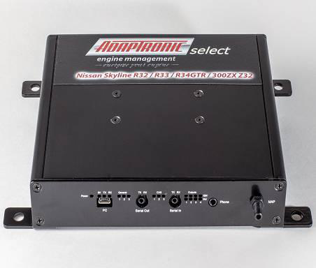
Adaptronic eSel015 is a Select-series vehicle plug-in programmable engine-management ECU. The surviving manufacturer guide identifies the intended application as Nissan Skyline R32 and R33 GTST/GTR, R34 GTR, and Z32 300ZX/Fairlady applications listed in the manufacturer guide; R34 GTT is a different eSel027 model. Adaptronic eSel015 application and installation guide.
Identification and application
Confirm the case label and part number, original ECU and loom connector, engine, market and any vehicle-specific equipment against the guide before purchase or installation. Vehicle wiring can vary, and a shared plug shape does not establish pin compatibility.
Software and installation
The Select family uses Adaptronic WARI software, which is listed in Haltech’s legacy Adaptronic downloads archive. Use the matching eSel015 guide and application-specific basemap; the guide documents installation, configuration and pin references. A plug-in ECU still requires configuration and tuning for the actual engine and equipment.
Wiring and pinout
The manufacturer eSel015 guide contains the model and application-specific connector information. Positions and functions can change by application, and factory function and Adaptronic function are separate columns in the guide. The manufacturer connector tables are transcribed below; verify hardware, jumpers and viewpoint before use.
Support and sources
Haltech states that Adaptronic operations ended in 2022. Refer to its Adaptronic notice and archived guides, and confirm current support and compatibility for used hardware. A verified product photograph for this exact part has not yet been added.
Manufacturer connector schedules
Transcribed from the Adaptronic eSel015 installation guide. Identify the 130 mm and 160 mm cases and the exact vehicle before using a schedule. For the 130 mm 300ZX application, manufacturer jumpers J8–J11 must be selected for 300ZX. The 160 mm 300ZX table leaves the Adaptronic function for pin 106 blank while its comment says it connects to +5 V; verify this apparent conflict with the manufacturer. The internal header tables are explicitly for the 160 mm model. In the vehicle-connector tables, “NC” is the source's designation for no factory loom connection; a blank Adaptronic entry means no connection to the Adaptronic ECU. A dash in the table reproduces a blank source field.
130 mm ECU fitted to Skyline
| Factory pin | Factory function | Adaptronic function | Comments |
|---|---|---|---|
| 101 | Injector for cylinder 1 | Injector Output 2 | Injectors for cyl 1 & 4 paired |
| 102 | NC | — | — |
| 103 | Injector for cylinder 3 | Injector Output 3 | Injectors for cyl 3 & 5 paired |
| 104 | Fuel pump voltage control | +5V output | Connected straight to +5V |
| 105 | Injector for cylinder 2 | Injector Output 1 | Injectors for cyl 2 & 6 paired |
| 106 | Fuel pump voltage control (GTR) | +5V output | Fuel pump voltage control 2 on GTR, connected straight to +5V |
| 107 | Injector ground | Power Ground | — |
| 108 | Injector ground | Power Ground | — |
| 109 | +12V Ignition In | Switched 12V in | Power to the ECU |
| 110 | Injector for cylinder 5 | Injector Output 3 | Injectors for cyl 3 & 5 paired |
| 111 | NC | — | — |
| 112 | Injector for cylinder 6 | Injector Output 1 | Injectors for cyl 2 & 6 paired |
| 113 | Variable valve timing (R33 GTST only) | Aux Output 3 | Can be used as spare output on GTR and R32 |
| 114 | Injector for cylinder 4 | Injector Output 2 | Injectors for cyl 1 & 4 paired |
| 115 | O2 sensor heater ground | Power Ground | Connected straight to ground |
| 116 | Injector ground | Power Ground | — |
| 1 | To Igniter for Cylinder 1 | Ignition output 1 | Plugs for 1 & 6 are fired together |
| 2 | To Igniter for Cylinder 5 | Ignition output 2 | Plugs for 2 & 5 are fired together |
| 3 | To Igniter for Cylinder 3 | Ignition output 3 | Plugs for 3 & 4 are fired together |
| 4 | Idle Control Valve | Aux Output 1 | — |
| 5 | Auto Transmission | Aux Temp input | — |
| 6 | NC | Aux Output 8 | Electrical fan enable on GTR only, otherwise spare output |
| 7 | Tacho out | Aux Output 6 | — |
| 8 | NC | External 0-5V input | Can be used as external input for 0-5V wideband O2 sensor |
| 9 | Aircon relay | Aux Output 4 | — |
| 10 | Ground | Power Ground | — |
| 11 | To Igniter for Cylinder 6 | Ignition output 1 | Plugs for 1 & 6 are fired together |
| 12 | To Igniter for Cylinder 2 | Ignition output 2 | Plugs for 2 & 5 are fired together |
| 13 | To Igniter for Cylinder 4 | Ignition output 3 | Plugs for 3 & 4 are fired together |
| 14 | Auto Transmission | Digital Input 6 | — |
| 15 | Auto Transmission | Digital Input 7 | — |
| 16 | ECCS relay | — | When pin 45 has 12V, this pin is pulled low to activate the ECCS main relay |
| 17 | NC | Digital Input 8 | — |
| 18 | Fuel pump relay | Aux Output 5 | — |
| 19 | Power steering load input | Digital Input 1 | Connects via J8 |
| 20 | Ignition system ground | Power Ground | — |
| 21 | TXD | Air Temp signal input on some 130mm ECUs (not connected on current ECUs) | Formerly available to add air temp signal, now open circuit |
| 22 | RXD | Aux Output 8 | Available as spare output |
| 23 | Knock sensor 1 signal (cylinders 1-3) | Knock input | Both knock sensors are connected together |
| 24 | Knock sensor 2 signal (cylinders 4-6) | Knock input | Both knock sensors are connected together |
| 25 | Boost control | Aux Output 2 | — |
| 26 | AFM GND | Sensor Ground | — |
| 27 | AFM signal | MAP signal input | AFM signal pin can be used for MAP signal when fitting an external MAP sensor |
| 28 | Engine Coolant Temperature | ECT signal input | — |
| 29 | O2/EGO sensor signal | O2/EGO signal input | For the GTR, this is the front O2/EGO sensor |
| 30 | Sensor ground | Sensor Ground | — |
| 31 | Clock | — | — |
| 32 | Check light | Aux Output 7 | — |
| 33 | NC | — | — |
| 34 | AFM Ground on GTR | Power ground | Connects via J9 |
| 35 | Front AFM signal on GTR | No connection | Connects via J10 |
| 36 | FICD solenoid input signal on R33, Air temp input on GTR | Air Temp signal input | Connects via J11. Connect external air temp signal to this wire instead of the FICD input. |
| 37 | NC | MVSS2 | Available as flex fuel input or rear right wheel speed |
| 38 | TPS signal | TPS signal input | A scaled version of this is output on pin 56 |
| 39 | NC | SVSS1 | Flex fuel or front left wheel speed |
| 40 | NC | SVSS2 | Front right wheel speed |
| 41 | 120 deg Cam Angle Sensor Signal | CAS 2 input | Variable-width pulses each period, for cylinder and TDC identification |
| 42 | 1 deg Cam Angle Sensor Signal | CAS 1 input | 1 degree pulses for calculating ignition timing |
| 43 | Starter | — | — |
| 44 | Neutral switch | Digital Input 5 | — |
| 45 | Ignition switch | +12V Ignition | When this switches to 12V, the ECCS main relay is activated (see pin 16) |
| 46 | Aircon request input | Digital Input 2 | — |
| 47 | Check pin on CONSULT connector | CAS3 | Available as flex fuel input |
| 48 | +5V out | +5V output | +5V power supply for TPS |
| 49 | Control unit power supply | — | — |
| 50 | Control unit ground | Power Ground | — |
| 51 | 120 deg Cam Angle Sensor Signal | CAS 2 input | Connected to pin 41 internally |
| 52 | 1 deg Cam Angle Sensor Signal | CAS 1 input | Connected to pin 42 internally |
| 53 | Vehicle Speed Signal | MVSS1 | Gearbox speed sensor, or rear left wheel speed |
| 54 | Throttle Valve Switch | — | — |
| 55 | Rear O2 sensor (GTR) | O2/EGO signal input | Connected to pin 29 internally |
| 56 | Throttle sensor output signal | TPS signal (scaled by jumper J6) | TPS output signal to ALSD / ATESSA |
| 57 | Exhaust Temperature Sensor, or throttle valve switch on GTR | Sensor Ground | — |
| 58 | Battery power supply | Constant power in | — |
| 59 | Control unit power supply | — | — |
| 60 | Control unit ground | Power Ground | — |
130 mm ECU fitted to 300ZX
| Factory pin | Factory function | Adaptronic function | Comments |
|---|---|---|---|
| 101 | Injector for cylinder 1 | Injector Output 2 | Injectors for cyl 1 & 6 paired |
| 102 | EGR Valve | — | — |
| 103 | Injector for cylinder 3 | Injector Output 3 | Injectors for cyl 2 & 3 paired |
| 104 | Fuel pump voltage control | +5V output | Connected straight to +5V |
| 105 | Injector for cylinder 5 | Injector Output 1 | Injectors for cyl 4 & 5 paired |
| 106 | NC | +5V output | Connected straight to +5V |
| 107 | Injector ground | Power Ground | — |
| 108 | Injector ground | Power Ground | — |
| 109 | +12V Ignition In | Switched 12V in | — |
| 110 | Injector for cylinder 2 | Injector Output 3 | Injectors for cyl 2 & 3 paired |
| 111 | Pressure Regulator Control Valve | — | — |
| 112 | Injector for cylinder 4 | Injector Output 1 | Injectors for cyl 4 & 5 paired |
| 113 | Variable valve timing | Aux Output 3 | — |
| 114 | Injector for cylinder 6 | Injector Output 2 | Injectors for cyl 1 & 6 paired |
| 115 | O2 sensor heater ground | Power Ground | Connected straight to ground |
| 116 | Injector ground | Power Ground | — |
| 1 | To Igniter for Cylinder 1 | Ignition output 1 | Plugs for 1 & 4 are fired together |
| 2 | To Igniter for Cylinder 2 | Ignition output 2 | Plugs for 2 & 5 are fired together |
| 3 | To Igniter for Cylinder 3 | Ignition output 3 | Plugs for 3 & 6 are fired together |
| 4 | Idle Control Valve | Aux Output 1 | — |
| 5 | Auto Transmission | Aux Temp input | — |
| 6 | NC | Aux Output 8 | Spare output available |
| 7 | Tacho out | Aux Output 6 | — |
| 8 | AIV control valve | External 0-5V input | Can be used as external input for 0-5V wideband O2 sensor |
| 9 | Aircon relay | Aux Output 4 | — |
| 10 | Ground | Power Ground | — |
| 11 | To Igniter for Cylinder 4 | Ignition output 1 | Plugs for 1 & 4 are fired together |
| 12 | To Igniter for Cylinder 5 | Ignition output 2 | Plugs for 2 & 5 are fired together |
| 13 | To Igniter for Cylinder 6 | Ignition output 3 | Plugs for 3 & 6 are fired together |
| 14 | Auto Transmission | Digital Input 6 | — |
| 15 | Auto Transmission | Digital Input 7 | — |
| 16 | ECCS relay | — | When pin 45 has 12V, this pin is pulled low to activate the ECCS main relay |
| 17 | NC | Digital Input 8 | — |
| 18 | Fuel pump relay | Aux Output 5 | — |
| 19 | Radiator fan relay | Aux Output 8 | Connects via J8 |
| 20 | Ignition system ground | Power Ground | — |
| 21 | RXD | Air Temp signal input on some 130mm ECUs (not connected on current ECUs) | Formerly available to add air temp signal, now open circuit |
| 22 | TXD | Aux Output 8 | Available as spare output |
| 23 | Knock sensor 1 signal (cylinders 1- 3) | Knock input | — |
| 24 | NC | Knock input | Not connected on Z32 |
| 25 | Boost control | Aux Output 2 | — |
| 26 | AFM GND | Sensor Ground | — |
| 27 | AFM signal | MAP signal input | AFM signal pin can be used for MAP signal when fitting an external MAP sensor |
| 28 | Engine Coolant Temperature | ECT signal input | — |
| 29 | O2/EGO sensor signal right bank | O2/EGO signal input | — |
| 30 | Sensor ground | Sensor Ground | — |
| 31 | Clock | — | — |
| 32 | Check light | Aux Output 7 | — |
| 33 | FICD solenoid input signal | — | — |
| 34 | Power steering load switch | Digital input 1 | Connects via J9 |
| 35 | Fuel pump voltage control | 5V | Connects via J10 |
| 36 | Fuel temperature sensor | Aux temp signal input | — |
| 37 | NC | MVSS2 | Available as flex fuel input or rear right wheel speed |
| 38 | TPS signal | TPS signal input | — |
| 39 | NC | SVSS1 | Flex fuel or front left wheel speed |
| 40 | NC | SVSS2 | Front right wheel speed |
| 41 | 120 deg Cam Angle Sensor Signal | CAS 2 input | Variable-width pulses each period, for cylinder and TDC identification |
| 42 | 1 deg Cam Angle Sensor Signal | CAS 1 input | 1 degree pulses for calculating ignition timing |
| 43 | Starter | — | — |
| 44 | Neutral switch | Digital Input 5 | — |
| 45 | Ignition switch | +12V Ignition | When this switches to 12V, the ECCS main relay is activated (see pin 16) |
| 46 | Aircon request input | Digital Input 2 | — |
| 47 | Check pin on CONSULT connector | CAS3 | Available as flex fuel input |
| 48 | +5V out | +5V output | +5V power supply for sensors |
| 49 | Control unit power supply | — | — |
| 50 | Control unit ground | Power Ground | — |
| 51 | 120 deg Cam Angle Sensor Signal | CAS 2 input | Connected to pin 41 |
| 52 | 1 deg Cam Angle Sensor Signal | CAS 1 input | Connected to pin 42 |
| 53 | Vehicle Speed Signal | MVSS1 | Gearbox speed sensor, or rear left wheel speed |
| 54 | Throttle Valve Switch | — | — |
| 55 | O2 sensor (right bank) | O2/EGO signal input | Connected to pin 29 |
| 56 | Auto Transmission | TPS signal (scaled by jumper J6) | TPS output signal for Skyline (not used on the 300ZX) |
| 57 | Throttle valve switch | Sensor Ground | — |
| 58 | Battery power supply | Constant power in | — |
| 59 | Control unit power supply | — | — |
| 60 | Control unit ground | Power Ground | — |
160 mm ECU fitted to Z32 300ZX
| Factory pin | Factory function | Adaptronic function | Comments |
|---|---|---|---|
| 101 | Injector for cylinder 1 | Injector Output 2 | Injectors for Cylinders 1 and 6 are paired |
| 102 | NC | — | — |
| 103 | Injector for cylinder 3 | Injector Output 3 | Injectors for Cylinders 3 and 2 are paired |
| 104 | Fuel pump voltage control | +5V output | Connected straight to +5V |
| 105 | Injector for cylinder 5 | Injector Output 1 | Injectors for Cylinders 4 and 5 are paired |
| 106 | NC | — | Connected straight to +5V |
| 107 | Injector ground | Power Ground | — |
| 108 | Injector ground | Power Ground | — |
| 109 | +12V Ignition In | Const 12V | Switched via ECCS relay |
| 110 | Injector for cylinder 2 | Injector Output 3 | Injectors for Cylinders 2 and 3 are paired |
| 111 | NC | — | — |
| 112 | Injector for cylinder 4 | Injector Output 1 | Injectors for Cylinders 4 and 5 are paired |
| 113 | Variable Valve Timing | Aux Output 3 | — |
| 114 | Injector for cylinder 6 | Injector Output 2 | Injectors for Cylinders 6 and 1 are paired |
| 115 | O2 sensor heater ground | Power Ground | Connected straight to ground |
| 116 | Injector ground | Power Ground | — |
| 1 | To Igniter for Cylinder 1 | Ignition output 1 | Plugs for Cylinders 1 and 4 are fired together in wasted spark |
| 2 | To Igniter for Cylinder 2 | Ignition output 2 | Plugs for Cylinders 2 and 5 are fired together in wasted spark |
| 3 | To Igniter for Cylinder 3 | Ignition output 3 | Plugs for Cylinders 3 and 6 are fired together in wasted spark |
| 4 | Idle Control Valve | Aux Output 1 | — |
| 5 | Auto Transmission | — | — |
| 6 | NC | Power Ground | Electrical fan enable on GTR only, connected straight to ground so it always runs |
| 7 | Tacho out | Aux Output 6 | — |
| 8 | NC | — | — |
| 9 | Aircon relay | Aux Output 4 | — |
| 10 | Ground | Power Ground | — |
| 11 | To Igniter for Cylinder 4 | Ignition output 1 | Plugs for Cylinders 1 and 4 are fired together in wasted spark |
| 12 | To Igniter for Cylinder 5 | Ignition output 2 | Plugs for Cylinders 2 and 5 are fired together in wasted spark |
| 13 | To Igniter for Cylinder 6 | Ignition output 3 | Plugs for Cylinders 3 and 6 are fired together in wasted spark |
| 14 | Auto Transmission | — | — |
| 15 | Auto Transmission | — | — |
| 16 | ECCS relay | — | When pin 45 has 12V, this pin is pulled low to activate the ECCS main relay |
| 17 | NC | — | — |
| 18 | Fuel pump relay | Aux Output 5 | — |
| 19 | Power steering load input | Digital Input 1 | — |
| 20 | Ignition system ground | Power Ground | — |
| 21 | TXD | — | — |
| 22 | RXD | — | — |
| 23 | Knock sensor 1 signal (cylinders 1- 3) | Knock input | Both knock sensors are connected to the one knock input |
| 24 | Knock sensor 2 signal (cylinders 4- 6) | Knock input | Both knock sensors are connected to the one knock input |
| 25 | Boost control | Aux Output 2 | — |
| 26 | AFM GND | Sensor Ground | — |
| 27 | AFM signal | MAP signal input | AFM signal pin can be used for MAP signal when fitting an external MAP sensor |
| 28 | Engine Coolant Temperature | ECT signal input | — |
| 29 | O2/EGO sensor signal | O2/EGO signal input | For the GTR, this is the front O2/EGO sensor |
| 30 | Sensor ground | Sensor Ground | — |
| 31 | Clock | — | — |
| 32 | Check light | Aux Output 7 | The Adaptronic leaves this off at all times by default, but this can be changed |
| 33 | Check Light | — | — |
| 34 | NC | — | AFM ground |
| 35 | NC | — | Front AFM signal |
| 36 | FICD solenoid input signal | Air Temp signal input | Air Temperature sensor |
| 37 | NC | — | — |
| 38 | TPS signal | TPS signal input | — |
| 39 | NC | — | — |
| 40 | NC | — | — |
| 41 | 120 deg Cam Angle Sensor Signal | CAS 2 input | Variable-width pulses each period, for cylinder and TDC identification |
| 42 | 1 deg Cam Angle Sensor Signal | CAS 1 input | 1 degree pulses for calculating ignition timing |
| 43 | Starter | — | — |
| 44 | Neutral switch | Digital Input 5 | — |
| 45 | Ignition switch | +12V Ignition | When this switches to 12V, the ECCS main relay is activated (see pin 16) |
| 46 | Aircon request input | Digital Input 2 | — |
| 47 | Check input | — | — |
| 48 | +5V out | +5V output | +5V power supply for sensors |
| 49 | Control unit power supply | — | — |
| 50 | Control unit ground | Power Ground | — |
| 51 | 120 deg Cam Angle Sensor Signal | CAS 2 input | Connected to pin 41 |
| 52 | 1 deg Cam Angle Sensor Signal | CAS 1 input | Connected to pin 42 |
| 53 | Vehicle Speed Signal | MVSS1 | — |
| 54 | Throttle Valve Switch | — | — |
| 55 | NC | O2/EGO signal input | Second (rear) O2/EGO sensor on GTR only |
| 56 | Throttle sensor output signal | TPS signal | TPS output signal to ALSD |
| 57 | Exhaust Temperature Sensor | Sensor Ground | Throttle valve switch power supply on GTR only |
| 58 | Battery power supply | — | — |
| 59 | Control unit power supply | — | — |
| 60 | Control unit ground | Power Ground | — |
160 mm ECU internal 8-pin header
| Header pin | Description | Comments |
|---|---|---|
| 1 | Sensor 5V supply | — |
| 2 | Sensor Ground | — |
| 3 | MAP signal | Connected to the Air Flow Meter signal pin (pin 27) |
| 4 | Air Temperature signal | Temperature sensors must be wired with one wire to sensor ground and the other wire to the ECU signal input |
| 5 | MVSS1 (gearbox speed sensor, or rear left wheel sped) | Connected to the one vehicle speed signal pin (pin 53) |
| 6 | MVSS2 (rear right wheel speed) | Also flex fuel |
| 7 | SVSS1 (front left wheel speed) | Also flex fuel |
| 8 | SVSS2 (front right wheel speed) | — |
160 mm ECU internal 6-pin header
| Header pin | Description | Comments |
|---|---|---|
| 1 | External 0-5V input signal | — |
| 2 | Aux Temperature signal | Temperature sensors must be wired with one wire to sensor ground and the other wire to the ECU signal input |
| 3 | Aux Output 8 | Low current and no PWM, for things like relay coils |
| 4 | Digital Input 6 | — |
| 5 | Digital Input 7 | — |
| 6 | Digital Input 8 | — |