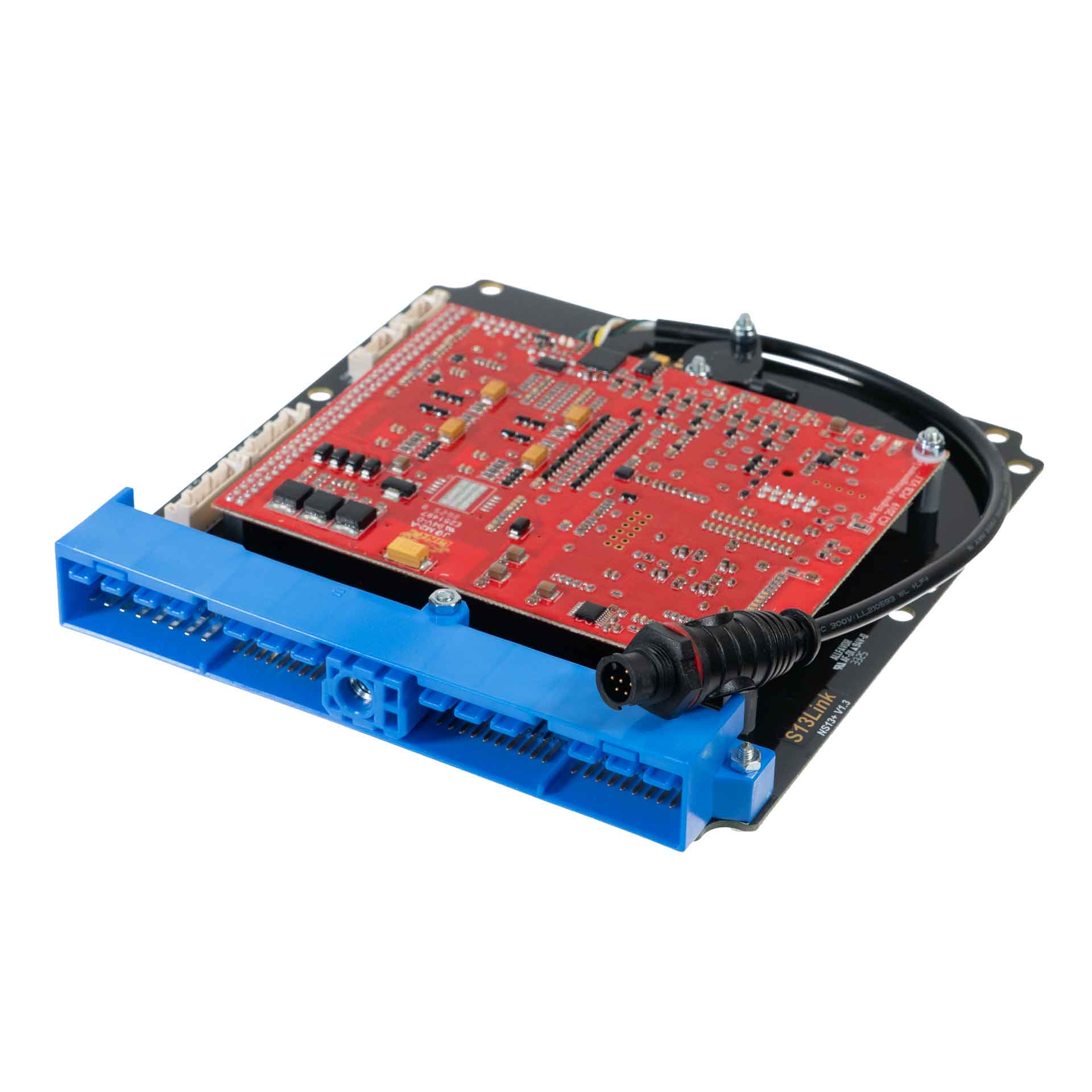
Link G4X NS13X is a vehicle-specific programmable plug-in ECU for the Nissan S13 application application listed in Link's model-specific manuals index. It is an application board, rather than the universal wire-in ECU. Check the exact vehicle, market, engine, original ECU and board part number against the manufacturer's NS13X installation manual.
Identification and installation
Record the Link model label and revision, donor factory ECU connector and car's engine and year. Plug-in boards connect to particular factory-harness layouts; the family or vehicle name alone does not establish every model-year or transmission combination. The manufacturer manual gives the supported application and any installation or configuration notes for this board.
G4X plug-in platforms offer configurable fuel and ignition control but available channels and features depend on the original header and board. The G4X plug-in general specifications are conditional on the particular application and do not mean every input is brought out to the factory harness.
Pinout and tuning
The NS13X installation manual is the model-specific source for board pinouts, expansion connections, electrical cautions and startup configuration. Use its connector orientation and the exact board version; do not copy a wire-in ECU pinout onto a factory harness. PCLink and manual downloads; Link manufacturer overview.
S13Link header and expansion connector schedules
From Link’s S13Link installation manual, pages 15–17. Link views the ECU from the wire side. The cited table distinguishes S13 CA18DET and S14 SR20DET uses; confirm the exact header and engine before wiring. Only source-listed positions are shown and “nc” is reproduced from Link.
| Pin | ECU channel | Vehicle function |
|---|---|---|
| 1 | Ignition 1 | Ignition |
| 2 | Ignition 2 | Ignition |
| 3 | Ignition 3 | Ignition |
| 4 | Injector 5 (Aux) | ISC solenoid |
| 5 | Aux 1 | Boost solenoid S13 CA18DET only |
| 6 | Injector 6 (Aux) | A/C out |
| 7 | Aux 2 | Tacho |
| 8 | Aux 3 | Intake runner control S13 CA18DET |
| 9 | Injector 6 (Aux) | A/C out |
| 10 | Ground | |
| 11 | Ignition 3 or 4 (via J1) | Ignition |
| 12 | Ignition 4 | Ignition |
| 13 | nc | |
| 14 | nc | |
| 15 | nc | |
| 16 | ECCS relay control | Pulls to ground with ignition on |
| 17 | nc | |
| 18 | Aux 4 | Fuel pump relay |
| 19 | Aux 3 | Engine fan low speed S14 SR20DET |
| 20 | Ground | |
| 21 | nc | |
| 22 | nc | |
| 23 | Knock 1 | Knock |
| 24 | nc | nc |
| 25 | Aux 6 | Boost solenoid S14 SR20DET |
| 26 | Ground | AFM |
| 27 | An Volt 4 | AFM signal |
| 28 | An Temp 1 | ECT |
| 29 | An Volt 1 | Oxygen signal |
| 30 | Ground (signal) | |
| 31 | nc | |
| 32 | Aux 7 | CE light S14 SR20DET |
| 33 | Aux 8 | CAT light / engine fan high S14 SR20DET |
| 34 | DI 1 | Power steering switch S14 SR20DET |
| 35 | An Volt 2 | Factory MAP sensor S14 SR20DET |
| 36 | nc | |
| 37 | nc | |
| 38 | An Volt 5 | TPS |
| 39 | nc | |
| 40 | nc | |
| 41 | Trig 2 | Trig 2 |
| 42 | Trig 1 | Trig 1 |
| 43 | DI 3 | Start signal |
| 44 | nc | |
| 45 | 12 V ignition switch input | Controls pin 16 |
| 46 | DI 4 | A/C in |
| 47 | nc | |
| 48 | +5 V Out | |
| 49 | +14 V ECCS relay | ECU power |
| 50 | Ground (signal) | |
| 51 | Trig 2 | Trig 2 |
| 52 | Trig 1 | Trig 1 |
| 53 | DI 2 | Vehicle speed |
| 54 | nc | |
| 55 | An Temp 2 | Factory IAT some S13 CA18DET |
| 56 | nc | |
| 57 | nc | |
| 58 | nc | |
| 59 | +14 V ECCS relay | ECU power |
| 60 | Ground (signal) | |
| 101 | Injector 1 | Injection |
| 102 | nc | |
| 103 | Injector 3 | Injection |
| 104 | nc | |
| 105 | nc | |
| 106 | Injector 5 (Aux) | ISC solenoid |
| 107 | Ground | |
| 108 | Ground | |
| 109 | +12 V constant | ISC flywheeling |
| 110 | Injector 2 | Injection |
| 111 | nc | |
| 112 | Injector 4 | Injection |
| 113 | Aux 5 | VTC cam solenoid S14 SR20DET |
| 114 | nc | |
| 115 | Ground | O2 heater |
| 116 | Ground |
Aux 3 appears on both 8 and 19 with different vehicle functions. Ignition 3 or 4 on 11 depends on jumper J1. Injector drives 7 and 8 are not exposed and lack injector-drive hardware. On-board MAP uses An Volt 3.
Expansion connector
| Pin | ECU channel |
|---|---|
| 1 | Ground (signal) |
| 2 | +5 V Out |
| 3 | DI 5 |
| 4 | DI 6 |
| 5 | DI 7 |
| 6 | An Volt 6 |
| 7 | An Temp 4 |
| 8 | An Temp 3 |
| 9 | Ignition 5 |
| 10 | Ignition 6 |
| 11 | Ignition 7 |
| 12 | Ignition 8 |
| 13 | An Volt 8 |
| 14 | An Volt 9 |
| 15 | An Volt 10 |
| 16 | An Volt 11 |
CAN 1 / RS232
| Pin | Function / cable colour |
|---|---|
| 1 | Comms GND (brown) |
| 2 | CAN1 L (green) |
| 3 | CAN1 H (white) |
| 4 | RS232 RX (grey) |
| 5 | RS232 TX (yellow) |
CAN 2 / OBD
| Pin | Function / cable colour |
|---|---|
| 1 | GND (brown) |
| 2 | CAN2 L (green) |
| 3 | CAN2 H (white) |
| 4 | NC (grey) |
| 5 | +14 V (yellow) |
Link cautions that connected serial wires can interfere with USB when CAN 1/RS232 is used for CAN.