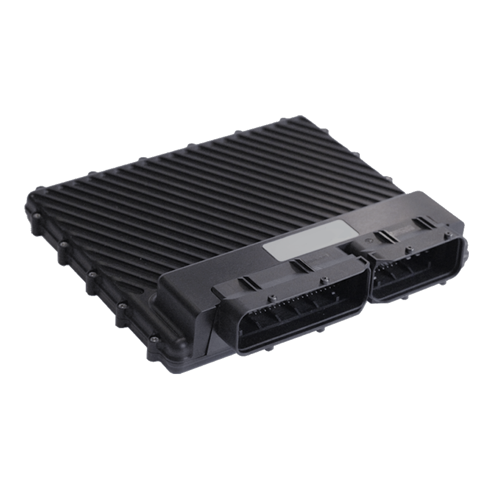
Model and vehicle application
Syvecs lists this vehicle-specific standalone or plug-in ECU kit as Audi R8 Gen1 V8 V10 S12, with product code S12-R8V8 / S12-R8V10. The product page and its stated vehicle, model and transmission details define this particular application; confirm market, model year, engine, ECU connector and transmission against Syvecs before ordering.
This entry describes the dedicated vehicle kit. It is distinct from the generic wire-in ECU: a plug-in kit can use application-specific adaptor wiring, a carrier, additional modules and an application calibration. The listed hardware or supported equipment can vary by revision.
Wiring and pinout
Syvecs Audi R8 Gen1 V8 V10 S12 installation and wiring document. Follow the connector orientation, application-specific tables, installation notes and hardware revision in this document. Do not transfer assignments from another vehicle merely because the underlying ECU family is similar. The link was checked to return a PDF.
For other variants and manual revisions consult the manufacturer's vehicle-specific manual index. Available spare inputs and outputs can be used only within their electrical limits and with a matching calibration.
Calibration and service
Use the correct Syvecs software, firmware and base calibration for the exact vehicle and installed hardware. The Syvecs software portal and firmware archive provide manufacturer support. A base map is a starting point and needs checking against the actual engine, injectors, sensors and modifications.
Sources
- Syvecs Audi R8 Gen1 V8 V10 S12 product listing and application
- Manufacturer kit installation and pinout manual
- Syvecs plug-in kit support index
R8 / LP560 kit S12 pin schedule
The Syvecs R8 / LP560 kit manual gives the following 121 S12 pin entries for its documented kit. The source combines ECU labels, SCal names and loom descriptions; fields are retained together, with its spelling and shared/configurable functions. It is a kit-specific schedule, not a general R8 factory ECU pinout; confirm V8 versus V10, loom and ECU revision with Syvecs. Use the original for electrical ratings and connector orientation.
| S12 pin | Manufacturer signal and application notes |
|---|---|
| 1 | PWRGND | Ecu Ground | Ground |
| 2 | IGN1 | Ignition (20A Open Collector) | IGN1 |
| 3 | IGN2 | Ignition (20A Open Collector) | IGN2 |
| 4 | IGN3 | Ignition (20A Open Collector) | IGN3 |
| 5 | IGN4 | Ignition (20A Open Collector) | IGN4 |
| 6 | IN25 | FUEL PRESSURE DI 2 |
| 7 | KNOCK4 | Knock Sensor 2 | Knock 4 |
| 8 | KNOCKGND | KNOCK GROUND |
| 9 | THERMO2 + |
| 10 | IN21 | Thermistor Input | AIR TEMP |
| 11 | IN18 | 5V Analogue Input | INTAKE MANIFOLD FLAP POT |
| 12 | IN14 | Configurable Analogue Input | FUEL PRESSURE LOW PRESSURE |
| 13 | IN11 | Configurable Analogue Input | TPS1A |
| 14 | IN7 | Configurable Analogue Input | TPS1B |
| 15 | IN4 | Configurable Analogue Input | External - MAP Sensor |
| 16 | IN1 | Configurable Analogue Input | CRUISE CONTROL |
| 17 | LAMI 1 | Red LSU |
| 18 | CAN LO 2 |
| 19 | RS232 TX |
| 20 | LAN RX- | Orange/White |
| 21 | FUEL 7 | Fuel Injector (10A Open Collector) | 12 Way DTM for Extra Injectors |
| 22 | FUEL 3 | Fuel Injector (10A Open Collector) | 12 Way DTM for Extra Injectors |
| 23 | VBAT | Main 12v |
| 24 | PWRGND | Ground |
| 25 | IN26 | 5V Analogue Input | PPS2 |
| 26 | 5V OUT | 5V OUT | 5V Out |
| 27 | KNK1 | KNOCK1 | KNOCK1 |
| 28 | THERO 1 - | THERO 1 - |
| 29 | IN22 | Thermistor Input | External – Air Charge Temp |
| 30 | IN19 | 5V | PPS1 |
| 31 | IN15 | Configurable Analogue Input | INTAKE MANIFOLD FLAP POT 2 |
| 32 | IN12 | Configurable Analogue Input | TPS2A |
| 33 | IN08 | Configurable Analogue Input | TPS2B |
| 34 | ANGND | SENSOR GROUND | Custom Loom for Map Sensor |
| 35 | IN02 | Configurable Analogue Input | Brake Servo Pressure |
| 36 | LAMV 1 | Black LSU |
| 37 | CAN HI 3 |
| 38 | RS232 RX |
| 39 | LAN RX+ | White/Orange |
| 40 | OUT8 | 12 Way DTM for Extra Injectors |
| 41 | OUT4 | 12 Way DTM for Extra Injectors |
| 42 | VBAT | Bank 1 and Bank 2 T14H connector pin 14 and custom loom for boost solenoid 12 V |
| 43 | PWRGND | Relay and canbridge ground |
| 44 | IN27 | 5V | FUEL PRESSURE DI |
| 45 | 5V OUT | TPS 5V, |
| 46 | KNOCK2 | Knock2 |
| 47 | THERMO1+ |
| 48 | IN23 | Thermistor Input | ENGINE COOLANT TEMP |
| 49 | IN20 | 5V | Steering Column Crank Signal |
| 50 | IN16 | Configurable Analogue Input |
| 51 | ANGND |
| 52 | IN09 | Configurable Analogue Input | Crank Signal |
| 53 | IN05 | Configurable Analogue Input |
| 54 | ANGND | T60 -28 | OIL TEMP, LOW FUEL PRESSURE, PPS |
| 55 | LAMV2 |
| 56 | CAN LO 3 |
| 57 | COMGND |
| 58 | CAN HI 1 | To Can Bridge X1 - Pin3 |
| 59 | LAN TX- | Green/White |
| 60 | OUT5 | VVT1 EXHAUST |
| 61 | OUT1 | VVT1 INLET |
| 62 | HBRIDGE5 |
| 63 | IN28 | 5V | BRAKE SIGNAL |
| 64 | 10VOUT |
| 65 | KNOCK 3 | Knock3 |
| 66 | THEMO 02 - |
| 67 | IN24 | Thermistor Input | ENGINE OIL TEMP |
| 68 | ANGND | CRANK SIG, TPS GROUNDS |
| 69 | IN17 | 5V | Park/Neutral Input from TCM |
| 70 | IN13 | Cam In1 |
| 71 | IN10 | Configurable Analogue Input | Cam ex1 |
| 72 | IN6 | Configurable Analogue Input | Cam In2 |
| 73 | IN3 | Configurable Analogue Input | Cam ex2 |
| 74 | LAMI 2 |
| 75 | LamGND | Yellow LSU |
| 76 | CAN HI 02 |
| 77 | CAN LO 1 | To Can Bridge X1 - Pin2 |
| 78 | LAN TX+ | White/Green |
| 79 | OUT6 | 12 Way DTM for Extra Injectors |
| 80 | OUT2 | 12 Way DTM for Extra Injectors |
| 81 | H BRIDGE 6 | Custom Loom for Boost Solenoid |
| 82 | H BRIDGE 1 | DBW 1 + |
| 83 | PWM4 | FUEL PUMPS |
| 84 | PWM8 | Brake Servo Relay |
| 85 | FUEL12 | 12 Way DTM for Extra Injectors |
| 86 | FUEL16 | 12 Way DTM for Extra Injectors |
| 87 | FUEL20 | VVT2 EXHAUST |
| 88 | FUEL24 | VVT2 INLET |
| 89 | VBAT | Main 12v |
| 90 | H BRIDGE 2 | DBW1 - |
| 91 | PWM3 | EXHAUST FLAPS |
| 92 | PWM7 | AUTOGEARBOX/PWRSTEERING SIGNAL |
| 93 | FUEL11 | 12 Way DTM for Extra Injectors |
| 94 | FUEL15 | 12 Way DTM for Extra Injectors |
| 95 | FUEL19 | INJECTOR 1 SIG |
| 96 | FUEL23 | INJECTOR 2 SIG |
| 97 | PWRGND |
| 98 | H BRIDGE 3 | DBW 2 + |
| 99 | PWM2 | Fan1 & 2 Signal |
| 100 | PWM6 | INTAKE MANIFOLD FLAP |
| 101 | FUEL10 | INJECTOR 3 SIG |
| 102 | FUEL14 | INJECTOR 4 SIG |
| 103 | FUEL18 | INJECTOR 5 SIG |
| 104 | FUEL22 | INJECTOR 6 SIG |
| 105 | PWRGND |
| 106 | HBRIDGE4 | DBW2 - |
| 107 | PWM1 | STARTER MOTOR RELAY |
| 108 | PWM5 | LAMBDA HEATERS |
| 109 | FUEL9 | INJECTOR 7 SIG |
| 110 | FUEL13 | INJECTOR 8 SIG |
| 111 | FUEL17 | INJECTOR 9 SIG |
| 112 | FUEL21 | INJECTOR 10 SIG |
| 113 | PWRGND |
| 114 | IGN5 | IGN5 |
| 115 | IGN6 | IGN6 |
| 116 | IGN7 | IGN7 |
| 117 | IGN8 | IGN8 |
| 118 | IGN9 | IGN9 |
| 119 | IGN10 | IGN10 |
| 120 | IGN11 | DI Spill Valve1 |
| 121 | IGN12 | Di Spill Valve2 |
Additional injector 12-way DTM
The same manual supplies this additional-injector breakout connector. It states that its two injector looms must connect to the black connectors, not the brown connectors.
| DTM terminal | Function |
|---|---|
| 1 | Fuel output 7 |
| 2 | Fuel output 3 |
| 3 | Fuel output 8 |
| 4 | Fuel output 4 |
| 5 | Fuel output 6 |
| 6 | Fuel output 2 |
| 7 | Fuel output 12 |
| 8 | Fuel output 16 |
| 9 | Fuel output 11 |
| 10 | Fuel output 15 |
| 11 | VBatt 12 V |
| 12 | VBatt 12 V |