Removed text is struck through; added text is highlighted.
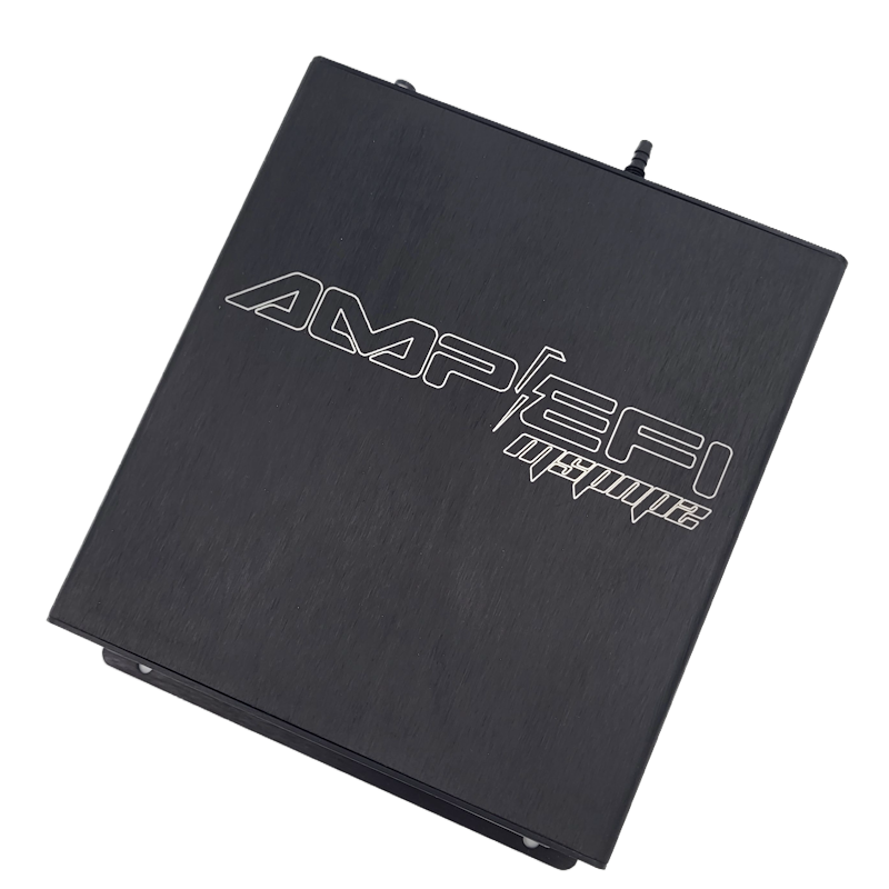
Manufacturer MSPNP2 product photograph used as a family illustration; vehicle-specific connectors and casing can differ. Image: AMP Engine Management; reproduced with permission.
MSPNP2 NS9501a is a vehicle-specific MegaSquirt-II-based plug-in ECU. The manufacturer’s documentation lists 1995 Nissan S14/240SX according to the manufacturer index. Confirm the ECU part number, engine, harness, region and transmission before use.
Application and version
The installation guide describes the combined 1995–1998 KA24 range; the manufacturer’s index distinguishes 1995 as NS9501a and 1996–1998 as NS9501b. This page describes the manufacturer’s version 2.0 documentation. Different hardware versions, optional jumpers and configurations can change installation details.
Installation and pinouts
Refer to the NS9501a version 2.0 installation guide for its model-specific wiring diagrams, connector orientation, sensor configuration and setup instructions. Check the exact installed configuration; avoid applying the pinout of an MS3Pro PNP or another vehicle. The manufacturer’s manual index also links older version documents.
Select and verify the correct base tune, check timing as directed and tune the specific engine after installation.
Rear options connector — V2.0
The 26-way auxiliary connector table below is transcribed from the manufacturer's application guide. These are option-connector letters, not the main vehicle ECU connector. Check the source diagram for viewing orientation, jumper instructions, device configuration and current limits.
PinFunctionManufacturer noteAADC1Ensure no jumpers installed in JP12–JP15 ADC1 positionsBADC2Ensure no jumpers installed in JP12–JP15 ADC2 positionsCExternal MAPMove JP6 jumper to EXTDIAT inputECam inputVR input 2FOxygen sensor inputEGO sensor port = LocalGTable switch inputSee jumper matrix JP14HKnock inputSee jumper matrix JP12IFlexRequires JP11 installedJClutch inputSee jumper matrix JP13K5 V referenceMaximum 0.5 ALSignal groundMCAN lowNOutput 2Incompatible if Spark C is usedOCAN highPOutput 1Incompatible if Spark D is usedQTachometer outputRBoostSee boost control sectionSSpark DIncompatible if Output 1 is usedTInjector DUSpark CIncompatible if Output 2 is usedVInjector CWSpark BXInjector BYSpark AZInjector A
The source guide does not establish every numbered vehicle connector assignment here; the table must not be used as a substitute for an application-specific OEM connector schedule.
Rendered revisions
Open each version to inspect formatting, tables and photographs.
Revision 2: MSPNP2 NS9501a — Nissan 240SX 1995
MSPNP2 NS9501a is a vehicle-specific MegaSquirt-II-based plug-in ECU. The manufacturer’s documentation lists 1995 Nissan S14/240SX according to the manufacturer index. Confirm the ECU part number, engine, harness, region and transmission before use.
Application and version
The installation guide describes the combined 1995–1998 KA24 range; the manufacturer’s index distinguishes 1995 as NS9501a and 1996–1998 as NS9501b. This page describes the manufacturer’s version 2.0 documentation. Different hardware versions, optional jumpers and configurations can change installation details.
Installation and pinouts
Refer to the NS9501a version 2.0 installation guide for its model-specific wiring diagrams, connector orientation, sensor configuration and setup instructions. Check the exact installed configuration; avoid applying the pinout of an MS3Pro PNP or another vehicle. The manufacturer’s manual index also links older version documents.
Select and verify the correct base tune, check timing as directed and tune the specific engine after installation.
Rear options connector — V2.0
The 26-way auxiliary connector table below is transcribed from the manufacturer's application guide. These are option-connector letters, not the main vehicle ECU connector. Check the source diagram for viewing orientation, jumper instructions, device configuration and current limits.
Pin
Function
Manufacturer note
A
ADC1
Ensure no jumpers installed in JP12–JP15 ADC1 positions
B
ADC2
Ensure no jumpers installed in JP12–JP15 ADC2 positions
C
External MAP
Move JP6 jumper to EXT
D
IAT input
E
Cam input
VR input 2
F
Oxygen sensor input
EGO sensor port = Local
G
Table switch input
See jumper matrix JP14
H
Knock input
See jumper matrix JP12
I
Flex
Requires JP11 installed
J
Clutch input
See jumper matrix JP13
K
5 V reference
Maximum 0.5 A
L
Signal ground
M
CAN low
N
Output 2
Incompatible if Spark C is used
O
CAN high
P
Output 1
Incompatible if Spark D is used
Q
Tachometer output
R
Boost
See boost control section
S
Spark D
Incompatible if Output 1 is used
T
Injector D
U
Spark C
Incompatible if Output 2 is used
V
Injector C
W
Spark B
X
Injector B
Y
Spark A
Z
Injector A
The source guide does not establish every numbered vehicle connector assignment here; the table must not be used as a substitute for an application-specific OEM connector schedule.
Revision 3: MSPNP2 NS9501a — Nissan 240SX 1995Manufacturer MSPNP2 product photograph used as a family illustration; vehicle-specific connectors and casing can differ. Image: AMP Engine Management; reproduced with permission.
MSPNP2 NS9501a is a vehicle-specific MegaSquirt-II-based plug-in ECU. The manufacturer’s documentation lists 1995 Nissan S14/240SX according to the manufacturer index. Confirm the ECU part number, engine, harness, region and transmission before use.
Application and version
The installation guide describes the combined 1995–1998 KA24 range; the manufacturer’s index distinguishes 1995 as NS9501a and 1996–1998 as NS9501b. This page describes the manufacturer’s version 2.0 documentation. Different hardware versions, optional jumpers and configurations can change installation details.
Installation and pinouts
Refer to the NS9501a version 2.0 installation guide for its model-specific wiring diagrams, connector orientation, sensor configuration and setup instructions. Check the exact installed configuration; avoid applying the pinout of an MS3Pro PNP or another vehicle. The manufacturer’s manual index also links older version documents.
Select and verify the correct base tune, check timing as directed and tune the specific engine after installation.
Rear options connector — V2.0
The 26-way auxiliary connector table below is transcribed from the manufacturer's application guide. These are option-connector letters, not the main vehicle ECU connector. Check the source diagram for viewing orientation, jumper instructions, device configuration and current limits.
Pin
Function
Manufacturer note
A
ADC1
Ensure no jumpers installed in JP12–JP15 ADC1 positions
B
ADC2
Ensure no jumpers installed in JP12–JP15 ADC2 positions
C
External MAP
Move JP6 jumper to EXT
D
IAT input
E
Cam input
VR input 2
F
Oxygen sensor input
EGO sensor port = Local
G
Table switch input
See jumper matrix JP14
H
Knock input
See jumper matrix JP12
I
Flex
Requires JP11 installed
J
Clutch input
See jumper matrix JP13
K
5 V reference
Maximum 0.5 A
L
Signal ground
M
CAN low
N
Output 2
Incompatible if Spark C is used
O
CAN high
P
Output 1
Incompatible if Spark D is used
Q
Tachometer output
R
Boost
See boost control section
S
Spark D
Incompatible if Output 1 is used
T
Injector D
U
Spark C
Incompatible if Output 2 is used
V
Injector C
W
Spark B
X
Injector B
Y
Spark A
Z
Injector A
The source guide does not establish every numbered vehicle connector assignment here; the table must not be used as a substitute for an application-specific OEM connector schedule.