Removed text is struck through; added text is highlighted.
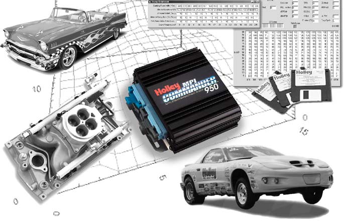
Commander 950 controller and system. Image from the Holley manufacturer manual, cover; reproduced with permission.
Holley Commander 950 is a legacy programmable EFI system with throttle-body and multiport arrangements and optional ignition timing control, depending on the ignition hardware. The Commander 950 hardware and tuning manual covers system types, connector wiring and ignition examples.
Ignition scope
The manual describes electronically controlled GM HEI, Ford TFI and crank-trigger/capacitive-discharge combinations. Non-computer-controlled inductive systems can supply RPM without giving the ECU timing control. Match the physical distributor, ignition box and harness to the original diagram rather than assuming all C950 installations control spark.
Software and support
Holley's legacy resources list Commander 950 software, tuning documentation and base maps. The listed legacy software has operating-system limitations; preserve the existing calibration and verify compatibility before editing.
See the Holley EFI manufacturer index. Sources reviewed 17 November 2026.
Commander 950 ECU connector scheduleThe following tables transcribe all 56 lettered and numbered ECU positions shown in figures 85–88 of the Holley Commander 950 Pro hardware and tuning manual, PDF pages 110–113. Figures 85, 86 and 87 cover GM TPI harness 271R865A, Holley SBC/BBC multiport 271R875A and Holley 4-barrel TBI 271R884A; figure 88 covers GM LT1/LT4 harness 271R886A. The figure 85 harness colours are shown where a wire is drawn. An empty colour field means no wire colour is shown in that diagram; “not used” is the source label for the illustrated build, not proof about every other harness. The diagrams describe connectors viewed from the end away from the wires. Check the precise ECU, harness and ignition arrangement against the complete schematic.The LT1/LT4 diagram labels D8 “NOSenable” and D9 “NOS1”, whereas figures 85–87 label D8 “NOT USED” and D9 “Output 1”. The other labels below reproduce figure 85; figure 88 uses “AC Request”, “Park / Neutral” and “Cooling Fan Relay” for B8, B10 and C1 respectively. Configurable and unconnected functions depend on the specific hardware and calibration.Connector APinFigure 85 functionFigure 85 harness colourA1Fuel Pump RelayGreen/BlackA2ModABrownA3ModBGreenA4NOT USEDA5NOT USEDA6Vswitch (switched power)Red/WhiteA7NOT USEDA8RxDYellowA9TxDOrangeA10Vehicle SpeedA11NOT USEDA12SERIAL GNDBlack/WhiteConnector BPinFigure 85 functionFigure 85 harness colourB1BatteryRedB2NOT USEDB3ECU GNDBlackB4MAPRed/BlackB5Ref / PIPYellow/BlackB6SlewFuelB7ESC (knock)B8AC Request / Input 1Orange/RedB9IPU (+)PurpleB10Park-Neutral / Input 2Dark BlueB11IPU (-)GreenB12SlewSparkConnector CPinFigure 85 functionFigure 85 harness colourC1Fan Relay / Output 2C2NOT USEDC3IAC "B" LoPurple/WhiteC4IAC "B" HiPurple/BlackC5IAC "A" HiPurple/YellowC6IAC "A" LoPurple/BlueC7NOT USEDC8NOT USEDC9Points OutWhiteC10Coolant TempBrownC11Coil (-)YellowC12MAT signalBlueC13TPS signalGreenC14+5 Volt refOrangeC15NOT USEDC16BatteryRedConnector DPinFigure 85 functionFigure 85 harness colourD1ECU GNDBlackD2Analog GNDBlack/WhiteD3Analog GNDBlack/WhiteD4EST / SPOUTBlue/WhiteD5BypassTan/BlackD6Analog GNDBlack/WhiteD7O2 Sensor signalPurpleD8NOT USEDD9Output 1D10ECU GNDBlackD11NOT USEDD12NOT USEDD13Injector AWhite/BlueD14Injector BWhite/RedD15Injector CWhite/BrownD16Injector DWhite/Green
Rendered revisions
Open each version to inspect formatting, tables and photographs.
Revision 2: Holley Commander 950Commander 950 controller and system. Image from the Holley manufacturer manual, cover; reproduced with permission.
Holley Commander 950 is a legacy programmable EFI system with throttle-body and multiport arrangements and optional ignition timing control, depending on the ignition hardware. The Commander 950 hardware and tuning manual covers system types, connector wiring and ignition examples.
Ignition scope
The manual describes electronically controlled GM HEI, Ford TFI and crank-trigger/capacitive-discharge combinations. Non-computer-controlled inductive systems can supply RPM without giving the ECU timing control. Match the physical distributor, ignition box and harness to the original diagram rather than assuming all C950 installations control spark.
Software and support
Holley's legacy resources list Commander 950 software, tuning documentation and base maps. The listed legacy software has operating-system limitations; preserve the existing calibration and verify compatibility before editing.
Revision 3: Holley Commander 950Commander 950 controller and system. Image from the Holley manufacturer manual, cover; reproduced with permission.
Holley Commander 950 is a legacy programmable EFI system with throttle-body and multiport arrangements and optional ignition timing control, depending on the ignition hardware. The Commander 950 hardware and tuning manual covers system types, connector wiring and ignition examples.
Ignition scope
The manual describes electronically controlled GM HEI, Ford TFI and crank-trigger/capacitive-discharge combinations. Non-computer-controlled inductive systems can supply RPM without giving the ECU timing control. Match the physical distributor, ignition box and harness to the original diagram rather than assuming all C950 installations control spark.
Software and support
Holley's legacy resources list Commander 950 software, tuning documentation and base maps. The listed legacy software has operating-system limitations; preserve the existing calibration and verify compatibility before editing.
The following tables transcribe all 56 lettered and numbered ECU positions shown in figures 85–88 of the Holley Commander 950 Pro hardware and tuning manual, PDF pages 110–113. Figures 85, 86 and 87 cover GM TPI harness 271R865A, Holley SBC/BBC multiport 271R875A and Holley 4-barrel TBI 271R884A; figure 88 covers GM LT1/LT4 harness 271R886A. The figure 85 harness colours are shown where a wire is drawn. An empty colour field means no wire colour is shown in that diagram; “not used” is the source label for the illustrated build, not proof about every other harness. The diagrams describe connectors viewed from the end away from the wires. Check the precise ECU, harness and ignition arrangement against the complete schematic.
The LT1/LT4 diagram labels D8 “NOSenable” and D9 “NOS1”, whereas figures 85–87 label D8 “NOT USED” and D9 “Output 1”. The other labels below reproduce figure 85; figure 88 uses “AC Request”, “Park / Neutral” and “Cooling Fan Relay” for B8, B10 and C1 respectively. Configurable and unconnected functions depend on the specific hardware and calibration.