Removed text is struck through; added text is highlighted.
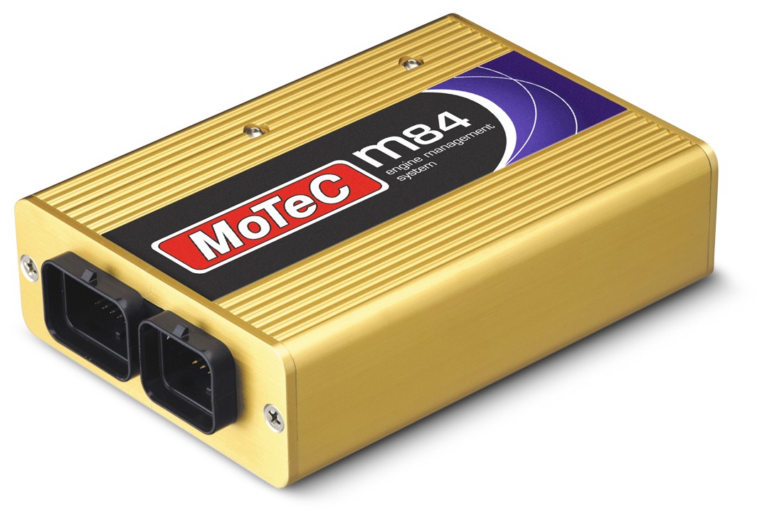
MoTeC M84 shown as an example of the Gold Box family; it is not the M880, whose connector configuration and details may differ. Image: MoTeC M84 datasheet; reproduced with permission.
MoTeC M880, part 13002, is an earlier Gold Box engine controller listed in MoTeC's obsolete-product archive. Up to twelve cylinders or four rotors with the appropriate configuration. Manufacturer Gold Box archive; manufacturer model glossary.
Identification and compatibility
Read the full ECU part number, connector, firmware, options and the label before identifying the correct model. Configurations and optional engine packages vary; a similar suffix, physical plug or a common calibration does not establish a universal pinout or exact cylinder capability. The manufacturer's archived product listing provides M880-specific documentation.
Pinout and software
Consult the MoTeC M880 product and wiring downloads and M400/M600/M800/M880 manufacturer manual. Model and marine-labelled variants must be checked against their own part numbers, connector drawings and firmware. Confirm connector orientation and the complete power, ground, sensor, injector and ignition circuits with the original documentation before wiring.
These units use a legacy ECU Manager or EMP software generation appropriate to the exact controller and firmware; M1 Tune is for M1 products. See MoTeC software archive and the MoTeC manufacturer guide.
Manufacturer connector pin list
From Appendix L of the MoTeC M400/M600/M800/M880 user manual (7 November 2003). This is the 66-position M880 connector; positions 20, 21 and 22 are not listed in this appendix. The appendix groups the M800 with the M400 and M600 on connectors A and B, not on this connector. Outputs marked * have no recirculation diode. Refer to the original connector view, wiring diagrams and electrical limits; output assignment may depend on model and configuration.A structured, redrawn version of the manufacturer pin list is in MoTeC M400, M600, M800 and M880 connector pinout.From Appendix L of the MoTeC M400/M600/M800/M880 user manual (7 November 2003). This is the 66-position M800/M880 connector; positions 20, 21 and 22 are not listed in this appendix. Outputs marked * have no recirculation diode. Refer to the original connector view, wiring diagrams and electrical limits; output assignment may depend on model and configuration.
PinDesignationFunction and model restrictions23,32,41VBATBattery positive14,15,19GNDBattery negative38V-ENG8 V engine sensor supply165V-ENG5 V engine sensor supply270V-ENGEngine sensor ground28V-AUX8 V auxiliary sensor and CAN supply345V-AUX5 V auxiliary sensor supply110V-AUXAuxiliary sensor ground9AUX1Auxiliary output 18AUX2Auxiliary output 243AUX3*Auxiliary output 351AUX4*Auxiliary output 459AUX5Auxiliary output 565AUX6Auxiliary output 658AUX7Auxiliary output 764AUX8Auxiliary output 81IGN1*Ignition output 15IGN2*Ignition output 24IGN3*Ignition output 310IGN4*Ignition output 417IGN5*Ignition output 5; not available on M40025IGN6*Ignition output 6; not available on M40033INJ1Injector output 150INJ2Injector output 263INJ3Injector output 366INJ4Injector output 424INJ5Injector output 5; not available on M40042INJ6Injector output 6; not available on M40057INJ7Injector output 7; not available on M400 or M60062INJ8Injector output 8; not available on M400 or M60026AV1Analogue voltage input 118AV2Analogue voltage input 26AV3Analogue voltage input 37AV4Analogue voltage input 412AV5Analogue voltage input 536AV6Analogue voltage input 635AV7Analogue voltage input 744AV8Analogue voltage input 828AT1Analogue temperature input 138AT2Analogue temperature input 230AT3Analogue temperature input 339AT4Analogue temperature input 429AT5Analogue temperature input 537AT6Analogue temperature input 646DIG1Digital input 145DIG2Digital input 252DIG3Digital input 353DIG4Digital input 449REFCrank reference timing input56SYNCCam sync timing input60LA1-PLambda 1 pump current54LA1-SLambda 1 sense voltage61LA2-PLambda 2 pump current; not available on M40055LA2-SLambda 2 sense voltage; not available on M40040TX-232RS232 transmit data31RX-232RS232 receive data47CAN-LOCAN bus low48CAN-HICAN bus high130V-COMCommunications ground
Rendered revisions
Open each version to inspect formatting, tables and photographs.
Revision 4: MoTeC M880MoTeC M84 shown as an example of the Gold Box family; it is not the M880, whose connector configuration and details may differ. Image: MoTeC M84 datasheet; reproduced with permission.
MoTeC M880, part 13002, is an earlier Gold Box engine controller listed in MoTeC's obsolete-product archive. Up to twelve cylinders or four rotors with the appropriate configuration. Manufacturer Gold Box archive; manufacturer model glossary.
Identification and compatibility
Read the full ECU part number, connector, firmware, options and the label before identifying the correct model. Configurations and optional engine packages vary; a similar suffix, physical plug or a common calibration does not establish a universal pinout or exact cylinder capability. The manufacturer's archived product listing provides M880-specific documentation.
Pinout and software
Consult the MoTeC M880 product and wiring downloads and M400/M600/M800/M880 manufacturer manual. Model and marine-labelled variants must be checked against their own part numbers, connector drawings and firmware. Confirm connector orientation and the complete power, ground, sensor, injector and ignition circuits with the original documentation before wiring.
These units use a legacy ECU Manager or EMP software generation appropriate to the exact controller and firmware; M1 Tune is for M1 products. See MoTeC software archive and the MoTeC manufacturer guide.
Manufacturer connector pin list
From Appendix L of the MoTeC M400/M600/M800/M880 user manual (7 November 2003). This is the 66-position M800/M880 connector; positions 20, 21 and 22 are not listed in this appendix. Outputs marked * have no recirculation diode. Refer to the original connector view, wiring diagrams and electrical limits; output assignment may depend on model and configuration.
Pin
Designation
Function and model restrictions
23,32,41
VBAT
Battery positive
14,15,19
GND
Battery negative
3
8V-ENG
8 V engine sensor supply
16
5V-ENG
5 V engine sensor supply
27
0V-ENG
Engine sensor ground
2
8V-AUX
8 V auxiliary sensor and CAN supply
34
5V-AUX
5 V auxiliary sensor supply
11
0V-AUX
Auxiliary sensor ground
9
AUX1
Auxiliary output 1
8
AUX2
Auxiliary output 2
43
AUX3*
Auxiliary output 3
51
AUX4*
Auxiliary output 4
59
AUX5
Auxiliary output 5
65
AUX6
Auxiliary output 6
58
AUX7
Auxiliary output 7
64
AUX8
Auxiliary output 8
1
IGN1*
Ignition output 1
5
IGN2*
Ignition output 2
4
IGN3*
Ignition output 3
10
IGN4*
Ignition output 4
17
IGN5*
Ignition output 5; not available on M400
25
IGN6*
Ignition output 6; not available on M400
33
INJ1
Injector output 1
50
INJ2
Injector output 2
63
INJ3
Injector output 3
66
INJ4
Injector output 4
24
INJ5
Injector output 5; not available on M400
42
INJ6
Injector output 6; not available on M400
57
INJ7
Injector output 7; not available on M400 or M600
62
INJ8
Injector output 8; not available on M400 or M600
26
AV1
Analogue voltage input 1
18
AV2
Analogue voltage input 2
6
AV3
Analogue voltage input 3
7
AV4
Analogue voltage input 4
12
AV5
Analogue voltage input 5
36
AV6
Analogue voltage input 6
35
AV7
Analogue voltage input 7
44
AV8
Analogue voltage input 8
28
AT1
Analogue temperature input 1
38
AT2
Analogue temperature input 2
30
AT3
Analogue temperature input 3
39
AT4
Analogue temperature input 4
29
AT5
Analogue temperature input 5
37
AT6
Analogue temperature input 6
46
DIG1
Digital input 1
45
DIG2
Digital input 2
52
DIG3
Digital input 3
53
DIG4
Digital input 4
49
REF
Crank reference timing input
56
SYNC
Cam sync timing input
60
LA1-P
Lambda 1 pump current
54
LA1-S
Lambda 1 sense voltage
61
LA2-P
Lambda 2 pump current; not available on M400
55
LA2-S
Lambda 2 sense voltage; not available on M400
40
TX-232
RS232 transmit data
31
RX-232
RS232 receive data
47
CAN-LO
CAN bus low
48
CAN-HI
CAN bus high
13
0V-COM
Communications ground
Revision 5: MoTeC M880MoTeC M84 shown as an example of the Gold Box family; it is not the M880, whose connector configuration and details may differ. Image: MoTeC M84 datasheet; reproduced with permission.
MoTeC M880, part 13002, is an earlier Gold Box engine controller listed in MoTeC's obsolete-product archive. Up to twelve cylinders or four rotors with the appropriate configuration. Manufacturer Gold Box archive; manufacturer model glossary.
Identification and compatibility
Read the full ECU part number, connector, firmware, options and the label before identifying the correct model. Configurations and optional engine packages vary; a similar suffix, physical plug or a common calibration does not establish a universal pinout or exact cylinder capability. The manufacturer's archived product listing provides M880-specific documentation.
Pinout and software
Consult the MoTeC M880 product and wiring downloads and M400/M600/M800/M880 manufacturer manual. Model and marine-labelled variants must be checked against their own part numbers, connector drawings and firmware. Confirm connector orientation and the complete power, ground, sensor, injector and ignition circuits with the original documentation before wiring.
These units use a legacy ECU Manager or EMP software generation appropriate to the exact controller and firmware; M1 Tune is for M1 products. See MoTeC software archive and the MoTeC manufacturer guide.
Manufacturer connector pin list
From Appendix L of the MoTeC M400/M600/M800/M880 user manual (7 November 2003). This is the 66-position M880 connector; positions 20, 21 and 22 are not listed in this appendix. The appendix groups the M800 with the M400 and M600 on connectors A and B, not on this connector. Outputs marked * have no recirculation diode. Refer to the original connector view, wiring diagrams and electrical limits; output assignment may depend on model and configuration.