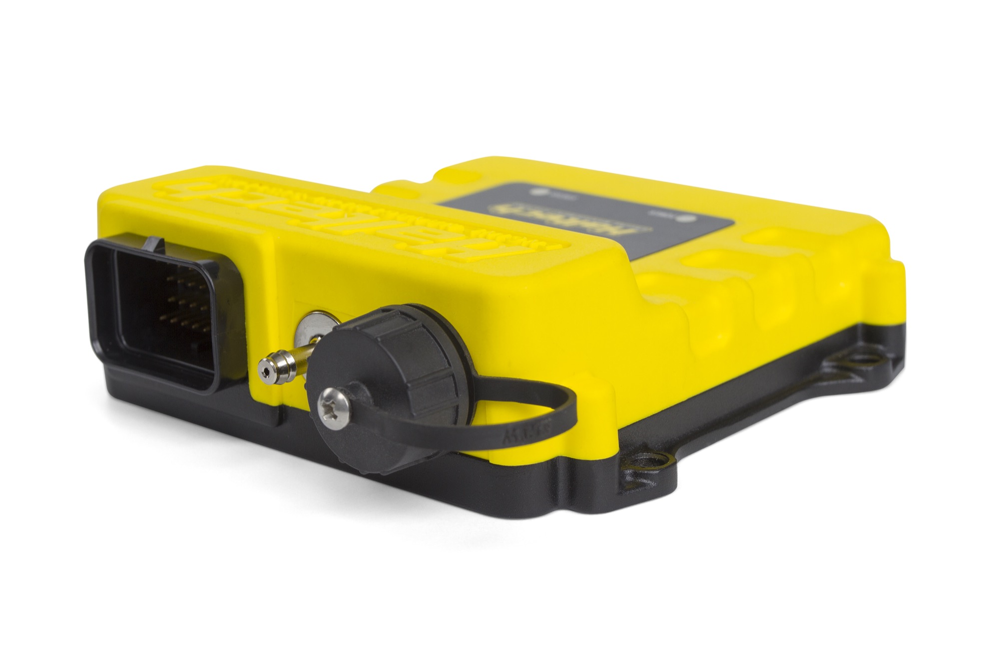
Haltech Elite VMS: Ignition-only Vehicle Management System for mechanically injected and carburetted drag-racing applications. Haltech describes eight ignition channels, two engine-position inputs, nine digital pulsed outputs, five analogue inputs and one CAN connection; it is not a standalone fuel-injection ECU. VMS does not have the VMS T model's advanced torque-management functionality. Haltech VMS / VMS T overview.
The manufacturer's overview lists a 34-position AMP connector, 8–16 V supply, USB communication and logging. Match the hardware and firmware to the actual vehicle, ignition modules and wiring.
VMS / VMS T connector pinout
Haltech publishes this shared 34-position table for VMS and VMS T. Use its connector illustration to establish orientation and its universal wiring diagram for circuits and limits.
| Pin | Function |
|---|---|
| 1 | DPO 2 |
| 2 | AVI 1 |
| 3 | IGN 1 |
| 4 | IGN 2 |
| 5 | IGN 3 |
| 6 | IGN 4 |
| 7 | IGN 5 |
| 8 | IGN 6 |
| 9 | +5 V DC |
| 10 | Battery ground |
| 11 | Signal ground |
| 12 | DPI 1 |
| 13 | DPI 2 |
| 14 | AVI 2 |
| 15 | AVI 3 |
| 16 | CAN high |
| 17 | CAN low |
| 18 | DPO 1 |
| 19 | DPO 6 |
| 20 | DPO 7 |
| 21 | DPO 8 |
| 22 | DPO 9 |
| 23 | DPO 3 |
| 24 | DPO 5 |
| 25 | DPO 4 |
| 26 | +13.8 V ECU power |
| 27 | IGN 7 |
| 28 | IGN 8 |
| 29 | AVI 4 |
| 30 | AVI 5 |
| 31 | Trigger + |
| 32 | Home + |
| 33 | Trigger − |
| 34 | Home − |
See Haltech model index. VMS and VMS T are retained here as related ignition-only products and should not be mistaken for full fuel-and-ignition ECUs.
34-way connector pinout
The Haltech Elite VMS / VMS T pinout lists the following positions and loom wire codes for both ignition-only units. Verify connector orientation, hardware and configured outputs with the original diagram.
| Pin | Wire colour code | Function |
|---|---|---|
| 1 | V/BR | DPO 2 |
| 2 | GY/Y | AVI 1 |
| 3 | Y/B | IGN 1 |
| 4 | Y/R | IGN 2 |
| 5 | Y/O | IGN 3 |
| 6 | Y/G | IGN 4 |
| 7 | Y/BR | IGN 5 |
| 8 | Y/L | IGN 6 |
| 9 | O | +5V DC |
| 10 | B | BATTERY GROUND |
| 11 | B/W | SIGNAL GROUND |
| 12 | GY <SHD> | DPI 1 |
| 13 | GY/B | DPI 2 |
| 14 | W | AVI 2 |
| 15 | Y | AVI 3 |
| 16 | W | CAN H |
| 17 | L | CAN L |
| 18 | V/B | DPO 1 |
| 19 | L | DPO 6 |
| 20 | L/B | DPO 7 |
| 21 | L/BR | DPO 8 |
| 22 | L/R | DPO 9 |
| 23 | V/R | DPO 3 |
| 24 | B/Y | DPO 5 |
| 25 | V/O | DPO 4 |
| 26 | R/L | +13.8V ECU PWR |
| 27 | Y/V | IGN 7 |
| 28 | Y/GY | IGN 8 |
| 29 | GY | AVI 4 |
| 30 | V | AVI 5 |
| 31 | Y (GY 4C) | TRIGGER + |
| 32 | Y (GY/B 4C) | HOME + |
| 33 | G (GY 4C) | TRIGGER - |
| 34 | G (GY/B 4C) | HOME - |