Removed text is struck through; added text is highlighted.
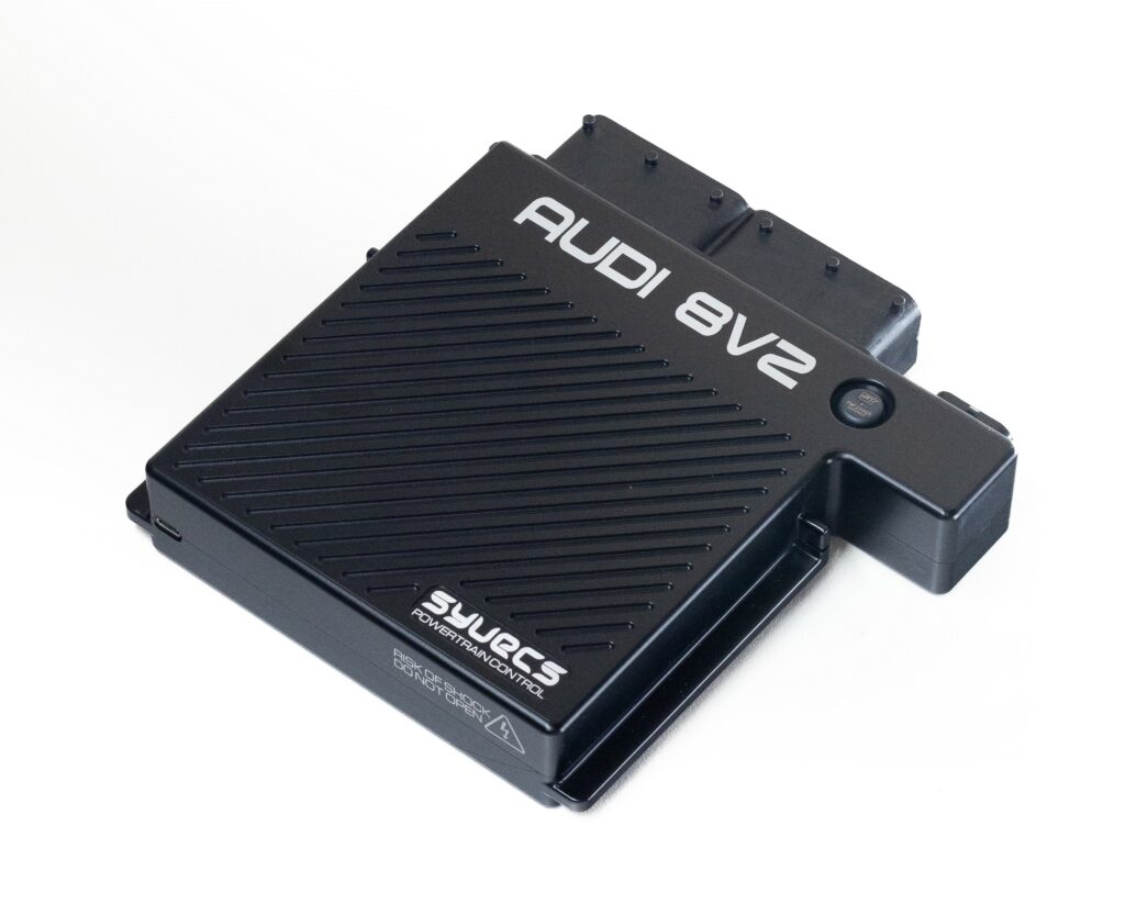
Audi 8V2 S7D plug-in ECU. Image: Syvecs product page, reproduced with permission.
Model and vehicle application
Syvecs lists this vehicle-specific standalone or plug-in ECU kit as Audi TTRS RS3 Mk3 8V2 S7D, with product code S7D-RS8V2DF. The product page and its stated vehicle, model and transmission details define this particular application; confirm market, model year, engine, ECU connector and transmission against Syvecs before ordering.
This entry describes the dedicated vehicle kit. It is distinct from the generic wire-in ECU: a plug-in kit can use application-specific adaptor wiring, a carrier, additional modules and an application calibration. The listed hardware or supported equipment can vary by revision.
Syvecs' product page links an 8Y2 guide despite this kit being labelled 8V2. Its manuals index lists a distinct 8V2 S7D guide, linked here. Verify the applicable document with the manufacturer.
Wiring and pinout
Syvecs Audi TTRS RS3 Mk3 8V2 S7D installation and wiring document. Follow the connector orientation, application-specific tables, installation notes and hardware revision in this document. Do not transfer assignments from another vehicle merely because the underlying ECU family is similar. The link was checked to return a PDF.
For other variants and manual revisions consult the manufacturer's vehicle-specific manual index. Available spare inputs and outputs can be used only within their electrical limits and with a matching calibration.
Calibration and service
Use the correct Syvecs software, firmware and base calibration for the exact vehicle and installed hardware. The Syvecs software portal and firmware archive provide manufacturer support. A base map is a starting point and needs checking against the actual engine, injectors, sensors and modifications.
Sources
Syvecs Audi TTRS RS3 Mk3 8V2 S7D product listing and applicationManufacturer kit installation and pinout manualSyvecs plug-in kit support index
RS3 8V2 S7D ECU and accessory connector schedulesThe Syvecs RS3 8V S7D kit manual gives these ECU connector and accessory connector positions. They are not the vehicle's OEM harness cavity numbers. Check the actual kit, hardware, connector view and electrical ratings in the manual.Source ambiguity: the source repeats lambda 1 names in several lambda 2 rows and identifies both ignition 4 and ignition 5 as N292. The rows below reproduce the manual's wording; seek Syvecs confirmation for the exact unit rather than assuming a correction.A connectorTerminalSyvecs labelFunction / OEM note in sourceA1PWR CTR OUTMain relay outputA2H-Bridge1DBW +A3H-Bridge2DBW −A4H-Bridge3Wastegate solenoidA5H-Bridge4EvapA6H-Bridge5Spare outputA7H-Bridge6Starter relayA8H-Bridge7Intake manifold flap N316A9H-Bridge8Coolant switch pumpA10GDI LS1Spare outputA11GDI LS2Injector 4−A12GDI LS3Port injector 1 N532A13GDI LS4Injector 2−A14GDI LS5Port injector 2 N533A15GDI LS6Injector 5−A16GDI LS7Port injector 3 N534A17GDI LS8Injector 3−A18GDI HS1/2Injector 4+A19GDI HS3/4Injector 2+A20GDI Pump 1 HSGDI pump high sideA21GDI HS5/6Injector 5+A22GDI HS7/8Injector 3+A23GDI Pump 2 HSInjector 1+A24GDI Pump 1 LowSideGDI pump low sideA25GDI Pump 2 LowSide / Injector LSInjector 1−A26IGN1Ignition 1 N70A27IGN2Ignition 2 N127A28IGN3Ignition 3 N291A29IGN4Ignition 4 N292A30IGN5Ignition 5 N292 (as printed)A31IGN6Tacho syncA32PWRGNDPower groundA33PWRGNDPower groundA34PWRGNDPower groundB connectorTerminalSyvecs labelFunction / OEM note in sourceB1PWRGNDPower groundB2CAN2 LCAN 2B3CAN2 HCAN 2B4KNOCK 1Knock 1B5KNOCK 2Knock 2B6PVBATConstant 12 VB7IVBAT12 VB8LAM1ALamV / LamD1+ / LamLun1B9LAM1BLamI / LamD1− / LamIP1B10LAM1CLamLIA1B11LAM1DLamGND / LamLVM1B12LAM1HEATERLambda heaterB13IVBAT12 VB14LAM2ALamV / LamD1+ / LamLun1B15LAM2BLamI / LamD1− / LamIP1B16LAM2CLamLIA1B17LAM2DLamGND / LamLVM1B18LAM2HEATERLambda heaterB19IVBAT12 VB20KLINEK-lineB21RS232RXRS232 RXB22RS232TXRS232 TXB23LANRX−Cat5 pin 2B24LANRX+Cat5 pin 1B25LANTX−Cat5 pin 6B26LANTX+Cat5 pin 3C connectorTerminalSyvecs labelFunction / OEM note in sourceC1KNOCKGNDKnock ground; OEM: Knock −C2ANGNDSensor ground; OEM: TestedC3ANGNDSensor ground; OEM: TestedC4ANGNDSensor groundC55V OUT5 V output; OEM: TestedC65V OUT5 V output; OEM: TestedC75V OUT5 V outputC8CAN1 LCAN 1 low; OEM: Powertrain CANC9CAN1 HCAN 1 high; OEM: Powertrain CANC10AN01Bipolar input; OEM: Start requestC11AN02Bipolar input; OEM: DI pressureC12AN03Bipolar inputC13AN04Bipolar inputC14AN05Unipolar input; OEM: VVT1 intake positionC15AN06Unipolar input; OEM: VVT1 exhaust positionC16AN07Unipolar input; OEM: Crank sensorC17AN08Unipolar input; OEM: Brake light switchC18AN09Voltage input; OEM: TPS1AC19AN10Voltage input; OEM: TPS1BC20AN11Voltage input; OEM: PPSAC21AN12Voltage input; OEM: PPSBC22AN13Resistive input; OEM: Coolant temperature G62C23AN14Resistive input; OEM: Intake air temperatureC24AN15Resistive input; OEM: EGT1C25AN16Resistive input; OEM: EGT2C26EGT1−EGT 1 negative; OEM: EGT1−C27EGT1+EGT 1 positive; OEM: EGT1+C28PWR CTR INMain relay input switch; OEM: Key-on signal 15C29AN S1Unipolar input; OEM: Intake position flapC30AN S2Unipolar input; OEM: Low-side fuel pressureC31AN S3Unipolar input; OEM: SENT MAPC32AN S4Unipolar input; OEM: SENT ACTC33AN S5Unipolar input; OEM: Pre-throttle MAPC34AN S6Unipolar input; OEM: Intermediate shaft speedD connectorTerminalSyvecs labelFunction / OEM note in sourceD1DVBAT1GDI power supplyD2DVBAT2GDI power supplyD3DVBAT3GDI power supplyD4DVBAT4GDI power supplyD5FUEL9PWM / fuel output; OEM: Port injector 4 N535D6FUEL10PWM / fuel output; OEM: Port injector 5 N536D7FUEL11PWM / fuel output; OEM: Fuel pump PWMD8FUEL12PWM / fuel output; OEM: Cooling fan PWMD9FUEL13PWM / fuel output; OEM: Turbo recirculation N249D10FUEL14PWM / fuel output; OEM: Exhaust cam solenoids AD11LSO1PWM output; OEM: VVT1 intake N205D12LSO2PWM output; OEM: VVT1 exhaust N316D13LSO3PWM output; OEM: Oil pressure valveD14LSO4PWM output; OEM: Crankcase breatherD15LSO5PWM output; OEM: Coolant shut-off valveD16LSO6PWM output; OEM: Coolant pump PWMD17EGT2−EGT 2 negativeD18EGT2+EGT 2 positiveD19NCNC in sourceD20NCNC in sourceD21NCNC in sourceD22NCNC in sourceD23CAN3LCAN 3 lowD24CAN3HCAN 3 highD25PWRGNDPower groundD26PWRGNDPower groundAccessory connectorTerminalSyvecs labelFunction / OEM note in sourceB1GNDGroundB2Fuel1Spare outputB3LSO3Spare output - Slave1 Out13B4LSO4Spare output - Slave1 Out14B5LSO5Spare output - Slave1 Out15B6LSO6Spare output - Slave1 Out16B712 VB8H-Bridge 5Spare output - Slave1 Out5B9CAN2LSpare CANB10CAN2HSpare CANB11RS232RXB12RS232TXB13LAM2ASpare input - S1AN08B14EGT1−K-type EGTB15EGT1+K-type EGTB16AN03Spare input - bipolarB17AN04Spare input - bipolarB18AN15Spare inputB19AN16Spare inputB20S1AN4Spare input if non-SENT MAP is usedB21ANGroundSensor groundB225V Out5 V output for sensorsB23Cat5 pin 2EthernetB24Cat5 pin 1EthernetB25Cat5 pin 6EthernetB26Cat5 pin 3Ethernet
Rendered revisions
Open each version to inspect formatting, tables and photographs.
Revision 2: Syvecs Audi TTRS RS3 Mk3 8V2 S7D Plug-in ECUAudi 8V2 S7D plug-in ECU. Image: Syvecs product page, reproduced with permission.
Model and vehicle application
Syvecs lists this vehicle-specific standalone or plug-in ECU kit as Audi TTRS RS3 Mk3 8V2 S7D, with product code S7D-RS8V2DF. The product page and its stated vehicle, model and transmission details define this particular application; confirm market, model year, engine, ECU connector and transmission against Syvecs before ordering.
This entry describes the dedicated vehicle kit. It is distinct from the generic wire-in ECU: a plug-in kit can use application-specific adaptor wiring, a carrier, additional modules and an application calibration. The listed hardware or supported equipment can vary by revision.
Syvecs' product page links an 8Y2 guide despite this kit being labelled 8V2. Its manuals index lists a distinct 8V2 S7D guide, linked here. Verify the applicable document with the manufacturer.
Wiring and pinout
Syvecs Audi TTRS RS3 Mk3 8V2 S7D installation and wiring document. Follow the connector orientation, application-specific tables, installation notes and hardware revision in this document. Do not transfer assignments from another vehicle merely because the underlying ECU family is similar. The link was checked to return a PDF.
For other variants and manual revisions consult the manufacturer's vehicle-specific manual index. Available spare inputs and outputs can be used only within their electrical limits and with a matching calibration.
Calibration and service
Use the correct Syvecs software, firmware and base calibration for the exact vehicle and installed hardware. The Syvecs software portal and firmware archive provide manufacturer support. A base map is a starting point and needs checking against the actual engine, injectors, sensors and modifications.
Revision 3: Syvecs Audi TTRS RS3 Mk3 8V2 S7D Plug-in ECUAudi 8V2 S7D plug-in ECU. Image: Syvecs product page, reproduced with permission.
Model and vehicle application
Syvecs lists this vehicle-specific standalone or plug-in ECU kit as Audi TTRS RS3 Mk3 8V2 S7D, with product code S7D-RS8V2DF. The product page and its stated vehicle, model and transmission details define this particular application; confirm market, model year, engine, ECU connector and transmission against Syvecs before ordering.
This entry describes the dedicated vehicle kit. It is distinct from the generic wire-in ECU: a plug-in kit can use application-specific adaptor wiring, a carrier, additional modules and an application calibration. The listed hardware or supported equipment can vary by revision.
Syvecs' product page links an 8Y2 guide despite this kit being labelled 8V2. Its manuals index lists a distinct 8V2 S7D guide, linked here. Verify the applicable document with the manufacturer.
Wiring and pinout
Syvecs Audi TTRS RS3 Mk3 8V2 S7D installation and wiring document. Follow the connector orientation, application-specific tables, installation notes and hardware revision in this document. Do not transfer assignments from another vehicle merely because the underlying ECU family is similar. The link was checked to return a PDF.
For other variants and manual revisions consult the manufacturer's vehicle-specific manual index. Available spare inputs and outputs can be used only within their electrical limits and with a matching calibration.
Calibration and service
Use the correct Syvecs software, firmware and base calibration for the exact vehicle and installed hardware. The Syvecs software portal and firmware archive provide manufacturer support. A base map is a starting point and needs checking against the actual engine, injectors, sensors and modifications.
The Syvecs RS3 8V S7D kit manual gives these ECU connector and accessory connector positions. They are not the vehicle's OEM harness cavity numbers. Check the actual kit, hardware, connector view and electrical ratings in the manual.
Source ambiguity: the source repeats lambda 1 names in several lambda 2 rows and identifies both ignition 4 and ignition 5 as N292. The rows below reproduce the manual's wording; seek Syvecs confirmation for the exact unit rather than assuming a correction.