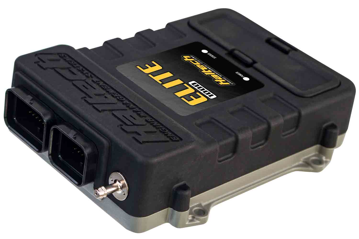
Haltech Elite 1000 is a Elite programmable engine-management model. Haltech specifies four fuel injection and four ignition outputs, programmable injector peak-and-hold current, up to two intake camshaft controls, single-channel knock control and dual CAN. Manufacturer specification or guide.
Identification and output allocation
Record the full ECU label, serial number, hardware or harness revision, software and existing calibration. These characteristics are model-specific; a superficially similar Elite ECU should not be treated as a drop-in replacement. Counts can be limited by shared outputs, external modules and the engine's ignition and injection strategy.
Model-specific pinout and wiring
Consult the Elite 1000 wiring documentation and the historic model manuals and connector archive where applicable. Select the named model and the precise harness revision; read its numbered connector view, driver characteristics, injector supply, power and ground notes. The connector appearance alone is not proof of identical pin functions.
Manufacturer connector tables
The following are the manufacturer-listed 34-way and 26-way connector assignments for the Elite 1000, including the loom wire-colour abbreviations used by Haltech. A dash is retained where the manufacturer does not list an assignment. Confirm ECU part number, connector view, software configuration and electrical limits against the linked original diagrams; do not transfer assignments from another model. On the 34-way plug, the ECU injector-power input is required for ECU operation.
34-way connector
Haltech Elite 1000 34-pin manufacturer pinout
| Pin | Wire colour code | Function in source |
|---|---|---|
| 1 | V/BR | DPO 2 |
| 2 | O/Y | AVI 4 |
| 3 | Y/B | IGN 1 |
| 4 | Y/R | IGN 2 |
| 5 | Y/O | IGN 3 |
| 6 | Y/G | IGN 4 |
| 7 | - | - |
| 8 | - | - |
| 9 | O | +5V DC |
| 10 | B | BATTERY GROUND |
| 11 | B | BATTERY GROUND |
| 12 | O/W | +8V DC |
| 13 | P | 12V IGNITION INPUT |
| 14 | W | AVI 10 ( TPS ) |
| 15 | Y | AVI 9 ( MAP ) |
| 16 | O/B | AVI 2 |
| 17 | O/R | AVI 3 |
| 18 | V/B | DPO 1 |
| 19 | L | INJ 1 |
| 20 | L/B | INJ 2 |
| 21 | L/BR | INJ 3 |
| 22 | L/R | INJ 4 |
| 23 | V/R | DPO 3 |
| 24 | B/Y | DPO 5 ( FUEL PUMP TRIGGER) |
| 25 | B/R | DPO 6 ( ECR OUT) |
| 26 | R/L | ECU INJECTOR POWER INPUT (REQUIRED CONNECTION FOR ECU TO OPERATE) |
| 27 | - | - |
| 28 | - | - |
| 29 | - | - |
| 30 | - | - |
| 31 | G | STEPPER 1 P1 / DPO |
| 32 | G/B | STEPPER 1 P2 / DPO |
| 33 | G/BR | STEPPER 1 P3 / DPO |
| 34 | G/R | STEPPER 1 P4 / DPO |
26-way connector
Haltech Elite 1000 26-pin manufacturer pinout
| Pin | Wire colour code | Function in source |
|---|---|---|
| 1 | Y (SHD) | CRANK (TRIGGER) ( + ) |
| 2 | Y (SHD) | CAM (HOME) ( + ) |
| 3 | GY | AVI 7 (AIR TEMP) |
| 4 | V | AVI 8 (COOLANT TEMP) |
| 5 | G (SHD) | CRANK (TRIGGER) ( - ) |
| 6 | G (SHD) | CAM (HOME) ( - ) |
| 7 | GY/R (SHD) | SPI 4 |
| 8 | GY (SHD) | SPI 1 |
| 9 | GY/B (SHD) | SPI 2 |
| 10 | GY/BR (SHD) | SPI 3 |
| 11 | R/W | +13.8V ECU SUPPLY (ECU POWER) |
| 12 | GY/O (SHD) | AVI 6 (O2 INPUT 1) |
| 13 | GY/Y (SHD) | AVI 1 (O2 INPUT 2 ) |
| 14 | B/W | SIGNAL GROUND |
| 15 | B/W | SIGNAL GROUND |
| 16 | B/W | SIGNAL GROUND |
| 17 | - | - |
| 18 | - | - |
| 19 | V/O | DPO 4 |
| 20 | O/G | AVI 5 |
| 21 | GY/G | KNOCK 1 |
| 22 | - | - |
| 23 | W | CAN H |
| 24 | L | CAN L |
| 25 | - | - |
| 26 | - | - |
Software and further information
ESP for Elite firmware 2.xx and NSP for Elite firmware 3.xx. Haltech's download centre separates software and provides a legacy section. See Haltech standalone ECUs for the other families.