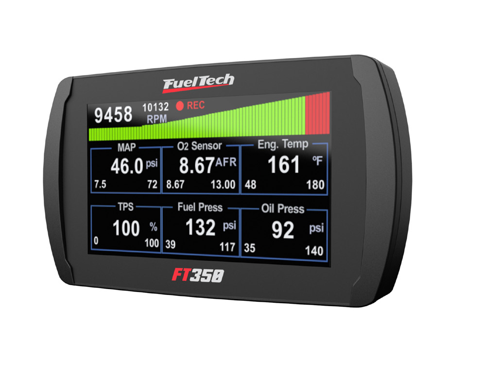
FuelTech FT350 is a Earlier FT generation engine-management unit. Early colour-touchscreen ECU with two injection banks, four auxiliary outputs, and configurable sensor inputs; the shared manual distinguishes it from FT400. FuelTech model documentation · FuelTech range comparison.
Identification and software
Record the exact model, serial, harness, firmware and configured outputs; similarly named FT models may use different connectors and functions. Tuning software: ECU Manager / Datalogger. FuelTech software and compatibility.
Wiring and pinout
Use the model-specific manual and the current FuelTech manuals index for connector view, cavity numbering, fuse values, sensor grounds and injector-driver limits. The manufacturer wiring archive contains installation-specific examples; match the exact ECU and harness before wiring. Pin functions depend on the model, hardware and configured output.
See FuelTech engine-management family for other models and company background. FuelTech is based in Brazil and has a US operation in Georgia. Sources reviewed 17 November 2026.
24-way main harness connector
Functions are from the FuelTech FT350 / FT400 manual, version 2.0, section 5.1. The source shows the rear of the harness connector. Inputs 2 and 4 have variant-specific recommended applications; check the model and configuration. Ground requirements in this manual differ from other FT generations.
| Pin | Function |
|---|---|
| 1 | Tachometer output (green) |
| 2 | Auxiliary output #3 (yellow 3) |
| 3 | Input 1 — intake air temperature (white/blue) |
| 4 | Auxiliary output #2 (yellow 2) |
| 5 | Input 2 — configurable sensor (white) |
| 6 | Auxiliary output #1 (yellow 1) |
| 7 | Input 3 — coolant temperature (pink) |
| 8 | Auxiliary output #4 (yellow 4) |
| 9 | Input 4 — configurable sensor (blue) |
| 10 | Ignition output E (gray E) |
| 11 | TPS signal / TPS 1 on electronic throttle (orange) |
| 12 | Ignition output D (gray D) |
| 13 | MAP signal output (yellow/red) |
| 14 | Ignition output C (gray C) |
| 15 | Camshaft position sensor input (green/yellow) |
| 16 | Ignition output B (gray B) |
| 17 | RPM signal input (shielded cable) |
| 18 | Ignition output A (gray A) |
| 19 | Battery negative / signal ground (black) |
| 20 | 5 V sensor supply (green/red) |
| 21 | Switched 12 V supply (red) |
| 22 | Power ground (black/white) |
| 23 | Fuel injector bank B negative (brown) |
| 24 | Fuel injector bank A negative (purple) |