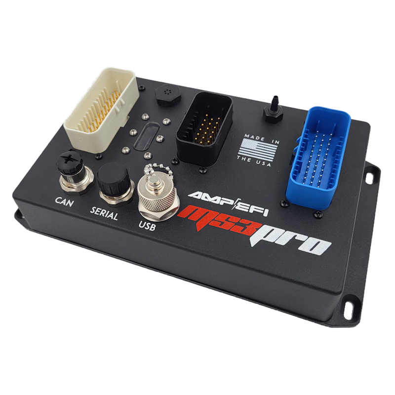
MS3Pro EVO Plus HC is a MegaSquirt-family engine-management product. The high-current version of EVO+ is identified separately by AMP EFI; DIYAutoTune lists up to 12 high-impedance injector outputs and eight high-current spark outputs. Other supplier package pages differ in spark count, so verify the actual unit and revision. Model source.
Identification and software
Record the ECU label, processor generation, board revision, firmware and installed hardware modifications. Calibration software and firmware must match the hardware. DIYAutoTune software and firmware · Model-specific information.
Wiring and pinout
Use the matching model document and wiring or support reference; the manufacturer manual index distinguishes wire-in and vehicle-specific variants. Check connector orientation, wiring changes, fuse ratings and output configuration before connecting loads; matching cases or software families do not establish identical pin functions.
See the MegaSquirt and MS3Pro family guide. Sources reviewed 17 November 2026.
ECU connector pin assignments
These positions follow the AMP EFI EVO+ / EVO+ HC manual (firmware 1.6.1) and its HC-specific wiring diagram, both linked from the manufacturer documentation index. The HC's high-current direct-coil drivers have different electrical characteristics from the standard EVO+ logic outputs: follow the HC-specific diagram, manual and coil guidance.
White connector — 35 way
| Pin | Function in source |
|---|---|
| 1 | High current out 1 |
| 2 | High current out 2 |
| 3 | Injector out J |
| 4 | Injector out I |
| 5 | High current out 3 |
| 6 | CKP+ |
| 7 | Knock In 2 |
| 8 | 5V+ VREF out |
| 9 | TPS in |
| 10 | MAT in |
| 11 | CLT in |
| 12 | Analog In 6 |
| 13 | Logic Ground |
| 14 | PWM / Idle Out 1 |
| 15 | CKP- |
| 16 | Ground |
| 17 | Analog In 7 |
| 18 | Sensor return |
| 19 | Analog in 1 |
| 20 | Analog in 2 |
| 21 | Analog in 3 |
| 22 | Analog In 4 |
| 23 | Analog In 5 |
| 24 | Tach out |
| 25 | O2 in |
| 26 | CMP+ |
| 27 | CMP- |
| 28 | Fuel pump relay out |
| 29 | PWM out 2 |
| 30 | PWM out 3 |
| 31 | Knock in 1 |
| 32 | Digital switched in 1 |
| 33 | CAN L |
| 34 | CAN H |
| 35 | 12V+ switched power in |
Gray / blue connector — 35 way
| Pin | Function in source |
|---|---|
| 1 | Injector out A |
| 2 | Injector out B |
| 3 | Ground |
| 4 | Injector out C |
| 5 | Ground |
| 6 | Injector out D |
| 7 | Ground |
| 8 | Injector out E |
| 9 | Ground |
| 10 | Injector out F |
| 11 | Injector out G |
| 12 | Injector out H |
| 13 | Spark out G |
| 14 | Spark out E |
| 15 | Spark out C |
| 16 | Spark out H |
| 17 | Digital frequency in 2 (Hall) |
| 18 | Ground |
| 19 | Digital switched 12V in |
| 20 | Digital switched in 2 |
| 21 | Digital frequency in 3 (unconditioned) |
| 22 | Digital Frequency in 3 (VR+) |
| 23 | Digital Frequency In 3 (VR-) |
| 24 | Spark out F |
| 25 | Spark out B |
| 26 | Spark out D |
| 27 | Spark out A |
| 28 | Digital frequency in 1 (unconditioned) |
| 29 | Digital switched in 3 |
| 30 | Stepper IAC out 1B |
| 31 | Stepper IAC out 1A |
| 32 | Stepper IAC out 2A |
| 33 | Stepper IAC out 2B |
| 34 | Digital Frequency in 1 (VR+) |
| 35 | Digital Frequency in 1 (VR-) |
Black connector — 23 way
| Pin | Function in source |
|---|---|
| 1 | PWM out 5 |
| 2 | PWM out 4 |
| 3 | Digital out 2 |
| 4 | Digital out 1 |
| 5 | Digital I/O 4 |
| 6 | Digital I/O 2 |
| 7 | Analog in 8 |
| 8 | No connection |
| 9 | No connection |
| 10 | Digital switched in 5 |
| 11 | Digital switched in 4 |
| 12 | Digital I/O 5 |
| 13 | Digital I/O 3 |
| 14 | Digital I/O 1 |
| 15 | 5V+ VREF out 2 |
| 16 | No connection |
| 17 | Sensor return |
| 18 | Sensor return |
| 19 | Sensor return |
| 20 | Sensor return |
| 21 | Sensor return |
| 22 | 5V+ VREF out 1 |
| 23 | No connection |
M12 serial service connector
M12 pins 1, 2, 3 and 4 map to DB9 pins 9 (5 V reference), 3 (data), 5 (ground) and 2 (data), respectively. Verify connector markings and adapter.