Removed text is struck through; added text is highlighted.
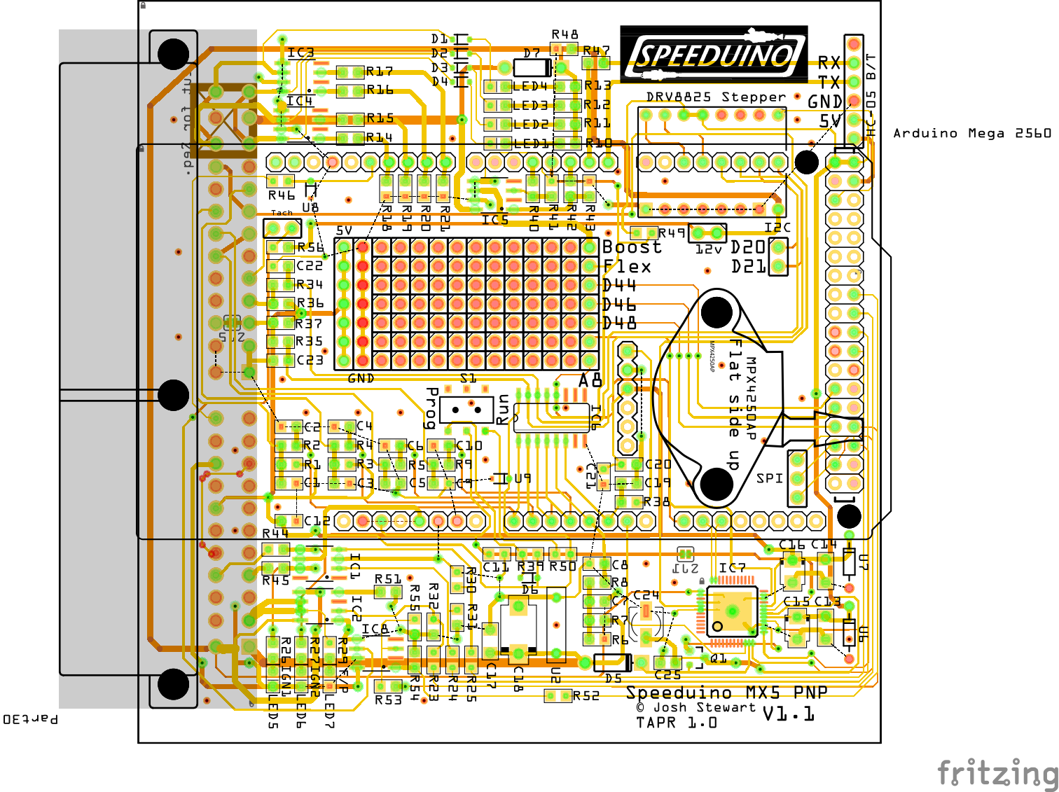
Speeduino MX-5 NA6 PCB design, version 1.1; the connector table below is for v1.3. Drawing by Josh Stewart, Speeduino hardware repository, distributed under its CERN-OHL-S licence.
The project NA6 plug-in replaces the factory 48-pin ECU on 1.6-litre NA cars from 1989–1993 and some 1.6-litre vehicles up to 1995. Check the original two-plug connector and vehicle wiring; year alone does not establish compatibility.
Installation and pinout source
The stock airflow meter is not operated by Speeduino. The project recommends a manifold-pressure connection, variable TPS and suitable intake-air-temperature sensor. Its guide states that the ST_SIG fuse must be removed for the documented stock fuel-pump control method. Consult the NA6-specific installation and wiring guide before powering the ECU. The official NA6 PCB files identify board revisions. The 48-pin car connector is not the universal v0.4 IDC connector.
Confirm exact assembled revision, modifications, controller and firmware before wiring. Sensor conditioning and compatible drivers matter; see project hardware requirements.
Factory connector — NA6 PCB revision 1.3
These labels and net names are transcribed from J1 on sheet 5 of the Speeduino NA6 v1.3 schematic. The schematic uses both a 1–48 symbol number and a factory-style cavity label; both are shown. “No connection shown” describes this PCB schematic only and does not establish that a vehicle loom cavity is empty. Confirm the PCB version, jumper settings and connector orientation in the original.
ROUT1 appears at both 2O and 2T on this schematic, with 2T annotated for an NA8 alternative fuel pump. The separate installation guide describes an alternative fuel pump method using 2O; verify the exact board, vehicle and jumper configuration. The manual's ST_SIG fuse instruction remains relevant for its documented primary fuel-pump setup.
Rendered revisions
Open each version to inspect formatting, tables and photographs.
Revision 2: Speeduino MX-5 NA6 PNP
The project NA6 plug-in replaces the factory 48-pin ECU on 1.6-litre NA cars from 1989–1993 and some 1.6-litre vehicles up to 1995. Check the original two-plug connector and vehicle wiring; year alone does not establish compatibility.
Installation and pinout source
The stock airflow meter is not operated by Speeduino. The project recommends a manifold-pressure connection, variable TPS and suitable intake-air-temperature sensor. Its guide states that the ST_SIG fuse must be removed for the documented stock fuel-pump control method. Consult the NA6-specific installation and wiring guide before powering the ECU. The official NA6 PCB files identify board revisions. The 48-pin car connector is not the universal v0.4 IDC connector.
Confirm exact assembled revision, modifications, controller and firmware before wiring. Sensor conditioning and compatible drivers matter; see project hardware requirements.
Factory connector — NA6 PCB revision 1.3
These labels and net names are transcribed from J1 on sheet 5 of the Speeduino NA6 v1.3 schematic. The schematic uses both a 1–48 symbol number and a factory-style cavity label; both are shown. “No connection shown” describes this PCB schematic only and does not establish that a vehicle loom cavity is empty. Confirm the PCB version, jumper settings and connector orientation in the original.
Schematic number
Cavity label
PCB net/function
1
1A
No connection shown
2
1C
ST_Sig
3
1E
No connection shown
4
1G
Ignition 1 output
5
1I
No connection shown
6
1K
No connection shown
7
1M
VSS
8
1O
No connection shown
9
1Q
AC-Jump
10
1S
No connection shown
11
1U
No connection shown
12
2A
Ground
13
2C
Ground
14
2E
Crank input
15
2G
Cam input
16
2I
Tachometer output
17
2K
No connection shown
18
2M
TPS sensor
19
2O
ROUT1
20
2Q
Coolant temperature sensor
21
2S
No connection shown
22
2U
Injector 1 output
23
2W
Idle output
24
2Y
Injector 3 output
25
1B
Switched 12 V / battery reference
26
1D
No connection shown
27
1F
No connection shown
28
1H
Ignition 2 output
29
1J
AC-Jump
30
1L
No connection shown
31
1N
VDDA
32
1P
No connection shown
33
1R
Fan output
34
1T
No connection shown
35
1V
Clutch input
36
2B
Ground
37
2D
Ground
38
2F
Crank input through jumper JP2
39
2H
No connection shown
40
2J
No connection shown
41
2L
TPS sensor
42
2N
Oxygen sensor
43
2P
Intake air temperature sensor
44
2R
No connection shown
45
2T
ROUT1, marked NA8 alternative fuel pump
46
2V
Injector 2 output
47
2X
Boost output
48
2Z
Injector 4 output
ROUT1 appears at both 2O and 2T on this schematic, with 2T annotated for an NA8 alternative fuel pump. The separate installation guide describes an alternative fuel pump method using 2O; verify the exact board, vehicle and jumper configuration. The manual's ST_SIG fuse instruction remains relevant for its documented primary fuel-pump setup.
Revision 3: Speeduino MX-5 NA6 PNPSpeeduino MX-5 NA6 PCB design, version 1.1; the connector table below is for v1.3. Drawing by Josh Stewart, Speeduino hardware repository, distributed under its CERN-OHL-S licence.
The project NA6 plug-in replaces the factory 48-pin ECU on 1.6-litre NA cars from 1989–1993 and some 1.6-litre vehicles up to 1995. Check the original two-plug connector and vehicle wiring; year alone does not establish compatibility.
Installation and pinout source
The stock airflow meter is not operated by Speeduino. The project recommends a manifold-pressure connection, variable TPS and suitable intake-air-temperature sensor. Its guide states that the ST_SIG fuse must be removed for the documented stock fuel-pump control method. Consult the NA6-specific installation and wiring guide before powering the ECU. The official NA6 PCB files identify board revisions. The 48-pin car connector is not the universal v0.4 IDC connector.
Confirm exact assembled revision, modifications, controller and firmware before wiring. Sensor conditioning and compatible drivers matter; see project hardware requirements.
Factory connector — NA6 PCB revision 1.3
These labels and net names are transcribed from J1 on sheet 5 of the Speeduino NA6 v1.3 schematic. The schematic uses both a 1–48 symbol number and a factory-style cavity label; both are shown. “No connection shown” describes this PCB schematic only and does not establish that a vehicle loom cavity is empty. Confirm the PCB version, jumper settings and connector orientation in the original.
Schematic number
Cavity label
PCB net/function
1
1A
No connection shown
2
1C
ST_Sig
3
1E
No connection shown
4
1G
Ignition 1 output
5
1I
No connection shown
6
1K
No connection shown
7
1M
VSS
8
1O
No connection shown
9
1Q
AC-Jump
10
1S
No connection shown
11
1U
No connection shown
12
2A
Ground
13
2C
Ground
14
2E
Crank input
15
2G
Cam input
16
2I
Tachometer output
17
2K
No connection shown
18
2M
TPS sensor
19
2O
ROUT1
20
2Q
Coolant temperature sensor
21
2S
No connection shown
22
2U
Injector 1 output
23
2W
Idle output
24
2Y
Injector 3 output
25
1B
Switched 12 V / battery reference
26
1D
No connection shown
27
1F
No connection shown
28
1H
Ignition 2 output
29
1J
AC-Jump
30
1L
No connection shown
31
1N
VDDA
32
1P
No connection shown
33
1R
Fan output
34
1T
No connection shown
35
1V
Clutch input
36
2B
Ground
37
2D
Ground
38
2F
Crank input through jumper JP2
39
2H
No connection shown
40
2J
No connection shown
41
2L
TPS sensor
42
2N
Oxygen sensor
43
2P
Intake air temperature sensor
44
2R
No connection shown
45
2T
ROUT1, marked NA8 alternative fuel pump
46
2V
Injector 2 output
47
2X
Boost output
48
2Z
Injector 4 output
ROUT1 appears at both 2O and 2T on this schematic, with 2T annotated for an NA8 alternative fuel pump. The separate installation guide describes an alternative fuel pump method using 2O; verify the exact board, vehicle and jumper configuration. The manual's ST_SIG fuse instruction remains relevant for its documented primary fuel-pump setup.