Overview and hardware
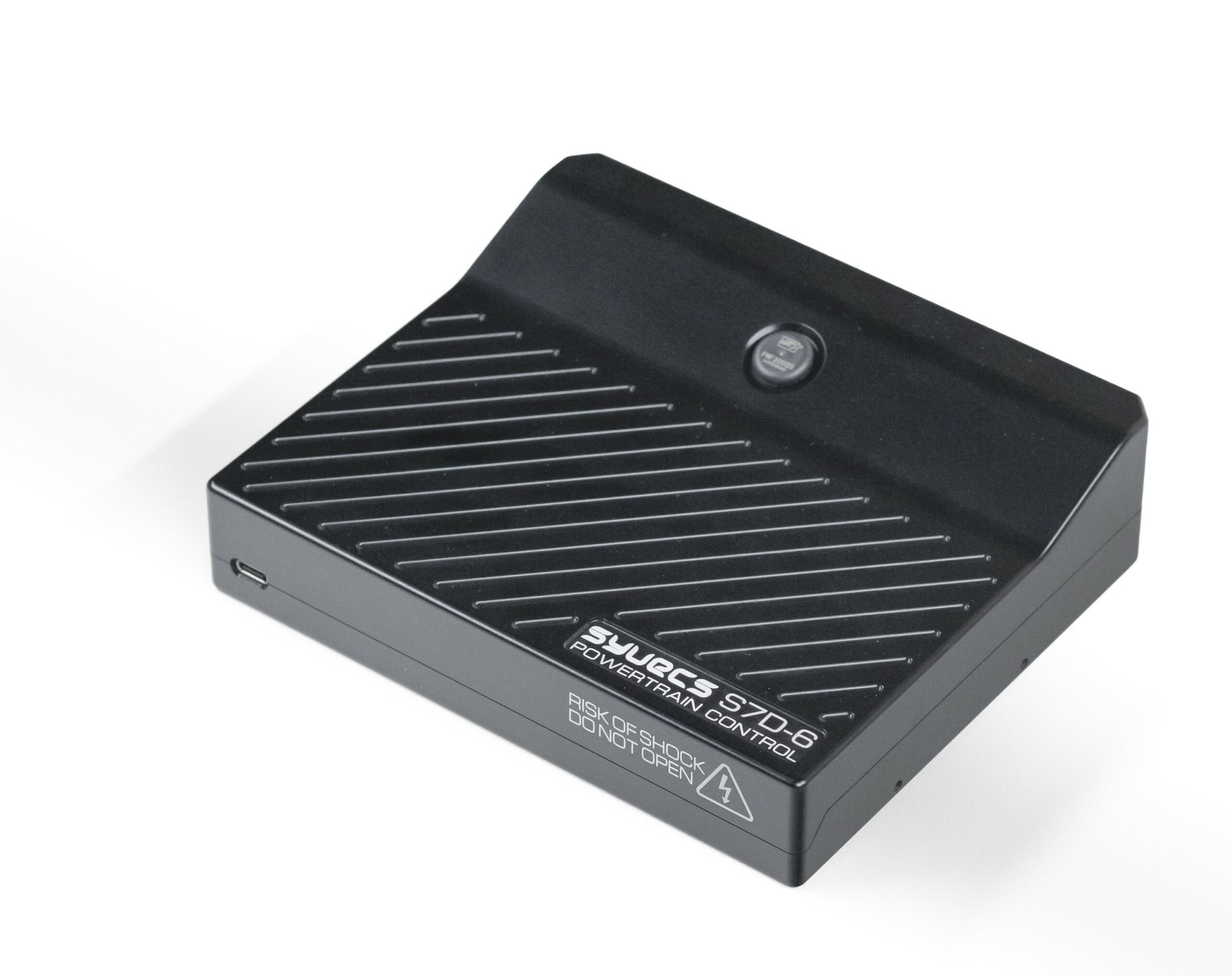
Syvecs S7D-6 is a British engine-management ECU. Six integrated DI channels and two DI pump outputs; 8 low-side port-injector outputs, 6 ignition and 6 extra low-side PWM. The 22 general-purpose inputs comprise 14 frequency, 4 ADC and 4 thermistor inputs; 2 wideband, 2 knock, 2 EGT, 3 CAN including CAN FD, 120 pins, 6–20 V. The comparison specifies six integrated channels despite the family product summary saying up to eight: confirm actual hardware.
Compare the required injector, ignition, actuator and sensor channels with the hardware available on the actual ECU. Capabilities and configurable functions depend on firmware, hardware revision and calibration.
Wiring and pinout
Manufacturer S7D-6 wiring guide and pinout. Use the guide's connector view and pin numbering and verify ECU hardware revision and configuration before wiring. Pin and input functions may vary by calibration or vehicle. Syvecs wiring index contains further example pinout files.
Vehicle-specific replacement kits use their own harness or carrier board. Consult the corresponding vehicle-specific Syvecs guide rather than assuming a generic schedule applies.
Complete connector pin assignments
All 94 positions below follow the Syvecs S7D-6 model-specific wiring guide, using the guide's source labels. N/A reproduces a source-marked unavailable position. Pin names describe hardware channels; assignments, software configuration, connector orientation, hardware options and electrical limits must be checked in that guide for the exact ECU.
The manufacturer describes ignition outputs as TTL by default with IGBT available as an option. The guide labels C4 as a sensor ground while its notes also say linked power ground; confirm grounding for the actual build. Direct-injector high- and low-side pairings must follow the specific diagram and electrical limits.
Connector A
| Pin | Source label |
|---|---|
| A1 | PWR CTR OUT |
| A2 | H‐Bridge1 |
| A3 | H‐Bridge2 |
| A4 | H‐Bridge3 |
| A5 | H‐Bridge4 |
| A6 | H‐Bridge5 |
| A7 | H‐Bridge6 |
| A8 | H‐Bridge7 |
| A9 | H‐Bridge8 |
| A10 | GDI LS1 |
| A11 | GDI LS2 |
| A12 | GDI LS3 |
| A13 | GDI LS4 |
| A14 | Fuel 5 |
| A15 | GDI LS6 |
| A16 | Fuel 7 |
| A17 | GDI LS8 |
| A18 | GDI HS1/2 |
| A19 | GDI HS3/4 |
| A20 | GDI Pump 1 HS |
| A21 | GDI HS5/6 |
| A22 | GDI HS7/8 |
| A23 | GDI Pump 2 HS |
| A24 | GDI Pump 1 LS |
| A25 | GDI Pump 2 LS |
| A26 | IGN1 |
| A27 | IGN2 |
| A28 | IGN3 |
| A29 | IGN4 |
| A30 | IGN5 |
| A31 | IGN6 |
| A32 | PWRGND |
| A33 | PWRGND |
| A34 | PWRGND |
Connector B
| Pin | Source label |
|---|---|
| B1 | PWRGND |
| B2 | CAN2 L |
| B3 | CAN2 H |
| B4 | KNOCK 1 |
| B5 | KNOCK 2 |
| B6 | PVBAT |
| B7 | IVBAT |
| B8 | LAM1A |
| B9 | LAM1B |
| B10 | LAM1C |
| B11 | LAM1D |
| B12 | LAM1HEATER |
| B13 | IVBAT |
| B14 | LAM2A |
| B15 | LAM2B |
| B16 | LAM2C |
| B17 | LAM2D |
| B18 | LAM2HEATER |
| B19 | IVBAT |
| B20 | KLINE |
| B21 | RS232RX |
| B22 | RS232TX |
| B23 | LAN RX− (Cat5 pin 2) |
| B24 | LAN RX+ (Cat5 pin 1) |
| B25 | LAN TX− (Cat5 pin 6) |
| B26 | LAN TX+ (Cat5 pin 3) |
Connector C
| Pin | Source label |
|---|---|
| C1 | KNOCKGND |
| C2 | ANGND |
| C3 | ANGND |
| C4 | ANGND |
| C5 | 5V OUT |
| C6 | 5V OUT |
| C7 | 5V OUT |
| C8 | CAN1 L |
| C9 | CAN1 H |
| C10 | AN01 |
| C11 | AN02 |
| C12 | AN03 |
| C13 | AN04 |
| C14 | AN05 |
| C15 | AN06 |
| C16 | AN07 |
| C17 | AN08 |
| C18 | AN09 |
| C19 | AN10 |
| C20 | AN11 |
| C21 | AN12 |
| C22 | AN13 |
| C23 | AN14 |
| C24 | AN15 |
| C25 | AN16 |
| C26 | EGT1‐ |
| C27 | EGT1+ |
| C28 | PWR CTR IN |
| C29 | AN S1 |
| C30 | AN S2 |
| C31 | AN S3 |
| C32 | AN S4 |
| C33 | AN S5 |
| C34 | AN S6 |
Calibration and sources
Syvecs uses SCal calibration software and provides firmware and base calibrations. Check version compatibility with the unit and preserve the existing tune before changes.