Removed text is struck through; added text is highlighted.
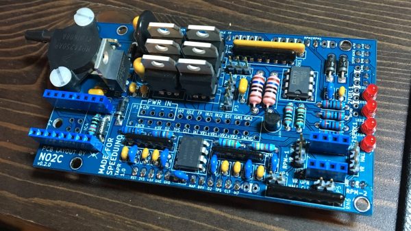
WTMtronics NO2C product image. Source: WTMtronics; reproduced with permission. Board revisions and kit contents may vary.
NO2C (No Overhang Two Channel) is an independently designed WTMtronics board using Speeduino firmware, not an official Speeduino project board. The designer documents two injector channels, two ignitor channels, VVT, PWM idle, boost, fuel-pump and tachometer outputs, two triggers, launch, CLT, IAT, TPS and O2 inputs, MAP and a socket for a stepper-idle module.
Versions and wiring
The designer’s NO2C revision files and project-hosted NO2C revision guide distinguish v0.1.x, v0.2.x, C1 and D1. The guide notes different connector families between v0.1 and v0.2. Obtain the schematic for the physical revision; do not substitute the 40-way v0.4 pinout. A board layout setting and firmware version must also match.
Connector assignments — NO2C vD1
The tables transcribe schematic connector labels from WTMtronics' NO2C vD1 schematic, sheet 1. These schematic position numbers must be matched to the PCB and mating connector orientation; other NO2C revisions and panel-mount wiring can differ. Check the trigger conditioner, output drivers and circuit ratings for the actual assembly.
Open each version to inspect formatting, tables and photographs.
Revision 2: WTMtronics NO2C for Speeduino
NO2C (No Overhang Two Channel) is an independently designed WTMtronics board using Speeduino firmware, not an official Speeduino project board. The designer documents two injector channels, two ignitor channels, VVT, PWM idle, boost, fuel-pump and tachometer outputs, two triggers, launch, CLT, IAT, TPS and O2 inputs, MAP and a socket for a stepper-idle module.
Versions and wiring
The designer’s NO2C revision files and project-hosted NO2C revision guide distinguish v0.1.x, v0.2.x, C1 and D1. The guide notes different connector families between v0.1 and v0.2. Obtain the schematic for the physical revision; do not substitute the 40-way v0.4 pinout. A board layout setting and firmware version must also match.
Connector assignments — NO2C vD1
The tables transcribe schematic connector labels from WTMtronics' NO2C vD1 schematic, sheet 1. These schematic position numbers must be matched to the PCB and mating connector orientation; other NO2C revisions and panel-mount wiring can differ. Check the trigger conditioner, output drivers and circuit ratings for the actual assembly.
P1 main 24-way
Schematic pin
Function
1
+BATT
2
Ground
3
Ground
4
Ground
5
VVT
6
Idle
7
Fuel pump
8
Injector 1
9
Injector 2
10
Boost
11
Ignition 1
12
Ignition 2
13
Launch
14
Ground
15
+5 V
16
O2
17
TPS
18
Coolant temperature
19
Intake air temperature
20
VR1+
21
VR1−
22
VR2+
23
VR2−
24
Tachometer
P2 stepper idle
Schematic pin
Function
1
Stepper A2
2
Stepper A1
3
Stepper B1
4
Stepper B2
P3 daughter-board power
Schematic pin
Function
1
+12 V
2
Ground
3
Ground
4
+5 V
P4 Bluetooth header
Schematic pin
Function
1
TX0
2
RX0
3
Ground
4
+5 V
Revision 3: WTMtronics NO2C for SpeeduinoWTMtronics NO2C product image. Source: WTMtronics; reproduced with permission. Board revisions and kit contents may vary.
NO2C (No Overhang Two Channel) is an independently designed WTMtronics board using Speeduino firmware, not an official Speeduino project board. The designer documents two injector channels, two ignitor channels, VVT, PWM idle, boost, fuel-pump and tachometer outputs, two triggers, launch, CLT, IAT, TPS and O2 inputs, MAP and a socket for a stepper-idle module.
Versions and wiring
The designer’s NO2C revision files and project-hosted NO2C revision guide distinguish v0.1.x, v0.2.x, C1 and D1. The guide notes different connector families between v0.1 and v0.2. Obtain the schematic for the physical revision; do not substitute the 40-way v0.4 pinout. A board layout setting and firmware version must also match.
Connector assignments — NO2C vD1
The tables transcribe schematic connector labels from WTMtronics' NO2C vD1 schematic, sheet 1. These schematic position numbers must be matched to the PCB and mating connector orientation; other NO2C revisions and panel-mount wiring can differ. Check the trigger conditioner, output drivers and circuit ratings for the actual assembly.