Removed text is struck through; added text is highlighted.
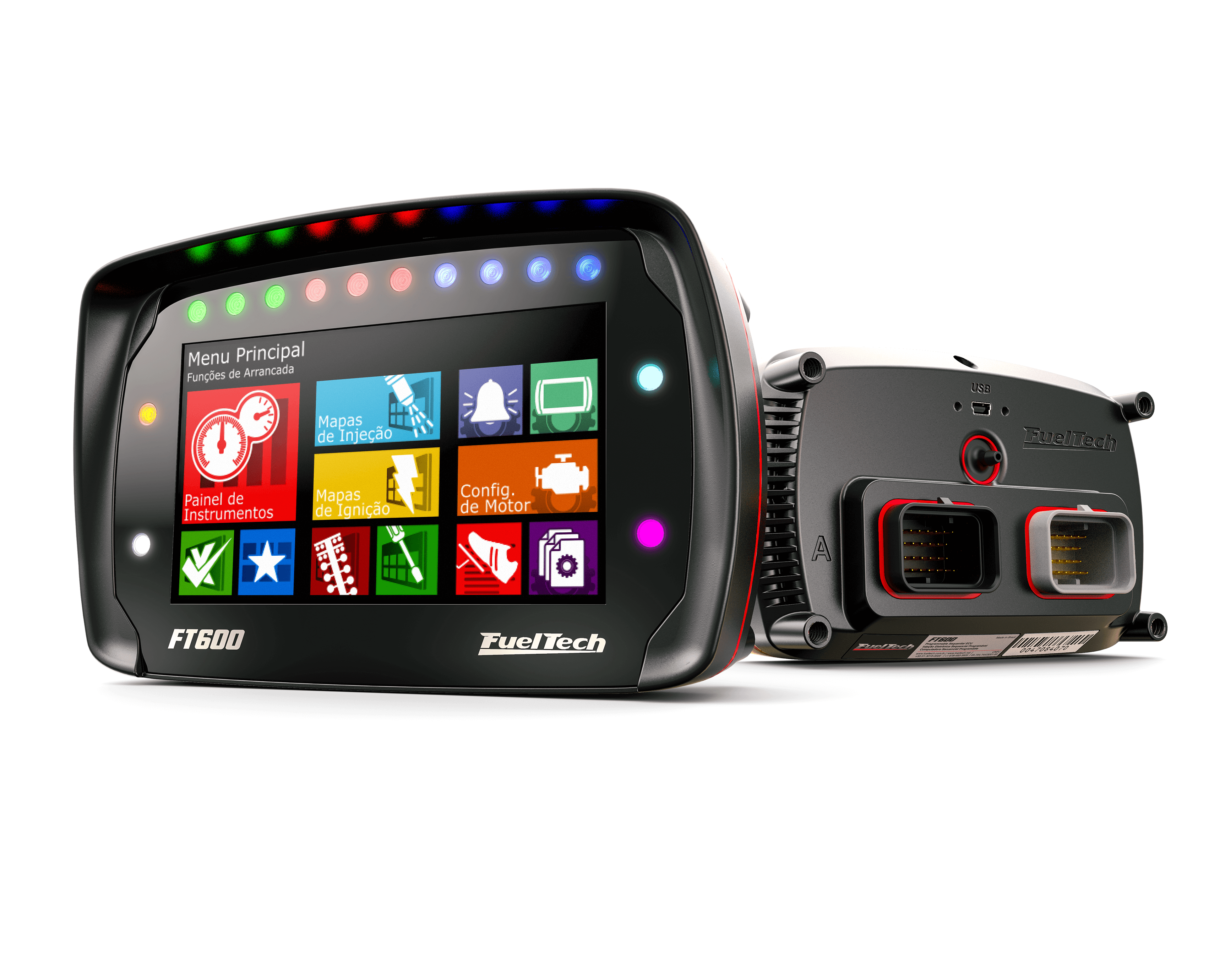
FT600. Image: FuelTech media kit; editorial and web use permitted.
FuelTech FT600 is a PowerFT engine-management unit. PowerFT ECU with 20 configurable inputs and 32 outputs, including support for up to 16 injector channels as configured. It integrates a display and data logging. FuelTech model documentation · FuelTech range comparison.
Identification and software
Record the exact model, serial, harness, firmware and configured outputs; similarly named FT models may use different connectors and functions. Tuning software: FTManager. FuelTech software and compatibility.
Wiring and pinout
Use the model-specific manual and the current FuelTech manuals index for connector view, cavity numbering, fuse values, sensor grounds and injector-driver limits. The manufacturer wiring archive contains installation-specific examples; match the exact ECU and harness before wiring. Pin functions depend on the model, hardware and configured output.
See FuelTech engine-management family for other models and company background. FuelTech is based in Brazil and has a US operation in Georgia. Sources reviewed 17 November 2026.
FT600 ECU connector pin assignments
The FuelTech FT600 manual, sections 4.3 and 4.4, identifies two 34-way ECU connectors. The listed sensor and output functions are configurable; use the exact revision and check the connector view, driver ratings, protection and ground routing in the original. The magnetic trigger references are not generic Hall sensor grounds.
PinFunction and harness wire1RPM signal input (red)2Magnetic RPM sensor reference (white)3Cam sync signal input (red)4Cam sync reference input (white)5White input #16White input #27White input #38White input #49White input #510Battery negative (black)11CAN A low (yellow/blue)12CAN A high (white/red)13White input #614White input #715White input #816White input #917White input #1018Power ground (black/white)19Power ground (black/white)20CAN B high (white/red)21White input #1122White input #1223White input #1324White input #1425White input #152612 V input from main relay (red)275 V sensor supply (green/red)28CAN B low (yellow/blue)29Sensor ground (green/black)30White input #1631White input #1732White input #1833White input #19 / Power Shift positive34White input #20 / Power Shift negative
Use the manual's power, grounding, relay and sensor instructions; power-ground and sensor-ground circuits have different functions. The optional Power Shift uses input channels 19 and 20 on this model.
Structured pinoutA structured pin index and redrawn connector diagrams for the FT450, FT550, FT550LITE and FT600 are in FuelTech FT450, FT550 and FT600 connector pinout.Not establishedThe microcontroller used in the PowerFT ECUs is not named in FuelTech's published documentation.
Rendered revisions
Open each version to inspect formatting, tables and photographs.
Revision 2: FuelTech FT600FT600. Image: FuelTech media kit; editorial and web use permitted.
FuelTech FT600 is a PowerFT engine-management unit. PowerFT ECU with 20 configurable inputs and 32 outputs, including support for up to 16 injector channels as configured. It integrates a display and data logging. FuelTech model documentation · FuelTech range comparison.
Identification and software
Record the exact model, serial, harness, firmware and configured outputs; similarly named FT models may use different connectors and functions. Tuning software: FTManager. FuelTech software and compatibility.
Wiring and pinout
Use the model-specific manual and the current FuelTech manuals index for connector view, cavity numbering, fuse values, sensor grounds and injector-driver limits. The manufacturer wiring archive contains installation-specific examples; match the exact ECU and harness before wiring. Pin functions depend on the model, hardware and configured output.
See FuelTech engine-management family for other models and company background. FuelTech is based in Brazil and has a US operation in Georgia. Sources reviewed 17 November 2026.
FT600 ECU connector pin assignments
The FuelTech FT600 manual, sections 4.3 and 4.4, identifies two 34-way ECU connectors. The listed sensor and output functions are configurable; use the exact revision and check the connector view, driver ratings, protection and ground routing in the original. The magnetic trigger references are not generic Hall sensor grounds.
Connector A — 34 way
Pin
Function and harness wire
1
Blue output #1 (blue #1)
2
Blue output #2 (blue #2)
3
Blue output #3 (blue #3)
4
Blue output #4 (blue #4)
5
Blue output #5 (blue #5)
6
Blue output #6 (blue #6)
7
Blue output #7 (blue #7)
8
Blue output #8 (blue #8)
9
Blue output #9 (blue #9)
10
Blue output #10 (blue #10)
11
Blue output #11 (blue #11)
12
Blue output #12 (blue #12)
13
Blue output #13 (blue #13)
14
Blue output #14 (blue #14)
15
Blue output #15 (blue #15)
16
Blue output #16 (blue #16)
17
Power ground (black/white)
18
Gray output #1 (gray #1)
19
Gray output #2 (gray #2)
20
Gray output #3 (gray #3)
21
Gray output #4 (gray #4)
22
Gray output #5 (gray #5)
23
Gray output #6 (gray #6)
24
Gray output #7 (gray #7)
25
Gray output #8 (gray #8)
26
Yellow output #1 (yellow #1)
27
Yellow output #2 (yellow #2)
28
Yellow output #3 (yellow #3)
29
Yellow output #4 (yellow #4)
30
Yellow output #5 (yellow #5)
31
Yellow output #6 (yellow #6)
32
Yellow output #7 (yellow #7)
33
Yellow output #8 (yellow #8)
34
12 V input from main relay (red)
Connector B — 34 way
Pin
Function and harness wire
1
RPM signal input (red)
2
Magnetic RPM sensor reference (white)
3
Cam sync signal input (red)
4
Cam sync reference input (white)
5
White input #1
6
White input #2
7
White input #3
8
White input #4
9
White input #5
10
Battery negative (black)
11
CAN A low (yellow/blue)
12
CAN A high (white/red)
13
White input #6
14
White input #7
15
White input #8
16
White input #9
17
White input #10
18
Power ground (black/white)
19
Power ground (black/white)
20
CAN B high (white/red)
21
White input #11
22
White input #12
23
White input #13
24
White input #14
25
White input #15
26
12 V input from main relay (red)
27
5 V sensor supply (green/red)
28
CAN B low (yellow/blue)
29
Sensor ground (green/black)
30
White input #16
31
White input #17
32
White input #18
33
White input #19 / Power Shift positive
34
White input #20 / Power Shift negative
Use the manual's power, grounding, relay and sensor instructions; power-ground and sensor-ground circuits have different functions. The optional Power Shift uses input channels 19 and 20 on this model.
Revision 3: FuelTech FT600FT600. Image: FuelTech media kit; editorial and web use permitted.
FuelTech FT600 is a PowerFT engine-management unit. PowerFT ECU with 20 configurable inputs and 32 outputs, including support for up to 16 injector channels as configured. It integrates a display and data logging. FuelTech model documentation · FuelTech range comparison.
Identification and software
Record the exact model, serial, harness, firmware and configured outputs; similarly named FT models may use different connectors and functions. Tuning software: FTManager. FuelTech software and compatibility.
Wiring and pinout
Use the model-specific manual and the current FuelTech manuals index for connector view, cavity numbering, fuse values, sensor grounds and injector-driver limits. The manufacturer wiring archive contains installation-specific examples; match the exact ECU and harness before wiring. Pin functions depend on the model, hardware and configured output.
See FuelTech engine-management family for other models and company background. FuelTech is based in Brazil and has a US operation in Georgia. Sources reviewed 17 November 2026.
FT600 ECU connector pin assignments
The FuelTech FT600 manual, sections 4.3 and 4.4, identifies two 34-way ECU connectors. The listed sensor and output functions are configurable; use the exact revision and check the connector view, driver ratings, protection and ground routing in the original. The magnetic trigger references are not generic Hall sensor grounds.
Connector A — 34 way
Pin
Function and harness wire
1
Blue output #1 (blue #1)
2
Blue output #2 (blue #2)
3
Blue output #3 (blue #3)
4
Blue output #4 (blue #4)
5
Blue output #5 (blue #5)
6
Blue output #6 (blue #6)
7
Blue output #7 (blue #7)
8
Blue output #8 (blue #8)
9
Blue output #9 (blue #9)
10
Blue output #10 (blue #10)
11
Blue output #11 (blue #11)
12
Blue output #12 (blue #12)
13
Blue output #13 (blue #13)
14
Blue output #14 (blue #14)
15
Blue output #15 (blue #15)
16
Blue output #16 (blue #16)
17
Power ground (black/white)
18
Gray output #1 (gray #1)
19
Gray output #2 (gray #2)
20
Gray output #3 (gray #3)
21
Gray output #4 (gray #4)
22
Gray output #5 (gray #5)
23
Gray output #6 (gray #6)
24
Gray output #7 (gray #7)
25
Gray output #8 (gray #8)
26
Yellow output #1 (yellow #1)
27
Yellow output #2 (yellow #2)
28
Yellow output #3 (yellow #3)
29
Yellow output #4 (yellow #4)
30
Yellow output #5 (yellow #5)
31
Yellow output #6 (yellow #6)
32
Yellow output #7 (yellow #7)
33
Yellow output #8 (yellow #8)
34
12 V input from main relay (red)
Connector B — 34 way
Pin
Function and harness wire
1
RPM signal input (red)
2
Magnetic RPM sensor reference (white)
3
Cam sync signal input (red)
4
Cam sync reference input (white)
5
White input #1
6
White input #2
7
White input #3
8
White input #4
9
White input #5
10
Battery negative (black)
11
CAN A low (yellow/blue)
12
CAN A high (white/red)
13
White input #6
14
White input #7
15
White input #8
16
White input #9
17
White input #10
18
Power ground (black/white)
19
Power ground (black/white)
20
CAN B high (white/red)
21
White input #11
22
White input #12
23
White input #13
24
White input #14
25
White input #15
26
12 V input from main relay (red)
27
5 V sensor supply (green/red)
28
CAN B low (yellow/blue)
29
Sensor ground (green/black)
30
White input #16
31
White input #17
32
White input #18
33
White input #19 / Power Shift positive
34
White input #20 / Power Shift negative
Use the manual's power, grounding, relay and sensor instructions; power-ground and sensor-ground circuits have different functions. The optional Power Shift uses input channels 19 and 20 on this model.