Removed text is struck through; added text is highlighted.
MS3Pro EVO Plus. Image: manufacturer product page; permission to republish confirmed by the user.
MS3Pro EVO Plus is a MegaSquirt-family engine-management product. The EVO+ uses three AMPSEAL connectors with 92 positions, an onboard 4-bar MAP sensor and barometric sensor; the supplier lists up to 12 high-impedance sequential injector outputs and up to 10 logic-level spark outputs. Model source.
Identification and software
Record the ECU label, processor generation, board revision, firmware and installed hardware modifications. Calibration software and firmware must match the hardware. DIYAutoTune software and firmware · Model-specific information.
Wiring and pinout
Use the matching model document and wiring or support reference; the manufacturer manual index distinguishes wire-in and vehicle-specific variants. Check connector orientation, wiring changes, fuse ratings and output configuration before connecting loads; matching cases or software families do not establish identical pin functions.
ECU connector pin assignments
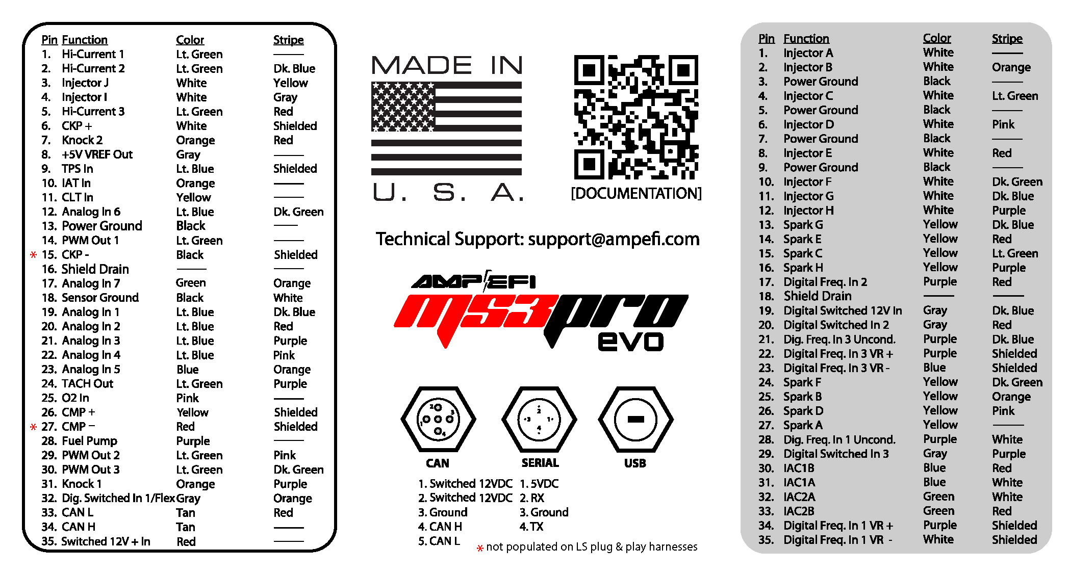
These tables reproduce the functions in the AMP EFI firmware 1.6.1 (2024) manual. Check the manual's connector view, harness colours, grounding and current limits against the actual ECU and firmware. Do not substitute the pinout of another MS3Pro generation: for example, the EVO and Ultimate manuals assign white connector positions 13 and 16 differently.
White, 35 way
PinFunction in source1High current out 12High current out 23Injector out J4Injector out I5High current out 36CKP+7Knock In 285V+ VREF out9TPS in10MAT in11CLT in12Analog In 613Logic Ground14PWM / Idle Out 115CKP-16Ground17Analog In 718Sensor return19Analog in 120Analog in 221Analog in 322Analog In 423Analog In 524Tach out25O2 in26CMP+27CMP-28Fuel pump relay out29PWM out 230PWM out 331Knock in 132Digital switched in 133CAN L34CAN H3512V+ switched power in
Gray, 35 way
PinFunction in source1Injector out A2Injector out B3Ground4Injector out C5Ground6Injector out D7Ground8Injector out E9Ground10Injector out F11Injector out G12Injector out H13Spark out G14Spark out E15Spark out C16Spark out H17Digital frequency in 2 (Hall)18Ground19Digital switched 12V in20Digital switched in 221Digital frequency in 3 (unconditioned)22Digital Frequency in 3 (VR+)23Digital Frequency In 3 (VR-)24Spark out F25Spark out B26Spark out D27Spark out A28Digital frequency in 1 (unconditioned)29Digital switched in 330Stepper IAC out 1B31Stepper IAC out 1A32Stepper IAC out 2A33Stepper IAC out 2B34Digital Frequency in 1 (VR+)35Digital Frequency in 1 (VR-)
Black, 23 way
PinFunction in source1PWM out 52PWM out 43Digital out 24Digital out 15Digital I/O 46Digital I/O 27Analog in 88No connection9No connection10Digital switched in 511Digital switched in 412Digital I/O 513Digital I/O 314Digital I/O 1155V+ VREF out 216No connection17Sensor return18Sensor return19Sensor return20Sensor return21Sensor return225V+ VREF out 123No connection
M12 serial service connector
The source lists M12 pins 1, 2, 3 and 4 to DB9 pins 9 (5 V reference), 3 (data), 5 (ground) and 2 (data), respectively. Verify the connector pin markings and use the matching adapter.
See the MegaSquirt and MS3Pro family guide. Sources reviewed 17 November 2026.
Rendered revisions
Open each version to inspect formatting, tables and photographs.
Revision 3: MS3Pro EVO PlusMS3Pro EVO Plus. Image: manufacturer product page; permission to republish confirmed by the user.
MS3Pro EVO Plus is a MegaSquirt-family engine-management product. The EVO+ uses three AMPSEAL connectors with 92 positions, an onboard 4-bar MAP sensor and barometric sensor; the supplier lists up to 12 high-impedance sequential injector outputs and up to 10 logic-level spark outputs. Model source.
Use the matching model document and wiring or support reference; the manufacturer manual index distinguishes wire-in and vehicle-specific variants. Check connector orientation, wiring changes, fuse ratings and output configuration before connecting loads; matching cases or software families do not establish identical pin functions.
ECU connector pin assignments
These tables reproduce the functions in the AMP EFI firmware 1.6.1 (2024) manual. Check the manual's connector view, harness colours, grounding and current limits against the actual ECU and firmware. Do not substitute the pinout of another MS3Pro generation: for example, the EVO and Ultimate manuals assign white connector positions 13 and 16 differently.
White, 35 way
Pin
Function in source
1
High current out 1
2
High current out 2
3
Injector out J
4
Injector out I
5
High current out 3
6
CKP+
7
Knock In 2
8
5V+ VREF out
9
TPS in
10
MAT in
11
CLT in
12
Analog In 6
13
Logic Ground
14
PWM / Idle Out 1
15
CKP-
16
Ground
17
Analog In 7
18
Sensor return
19
Analog in 1
20
Analog in 2
21
Analog in 3
22
Analog In 4
23
Analog In 5
24
Tach out
25
O2 in
26
CMP+
27
CMP-
28
Fuel pump relay out
29
PWM out 2
30
PWM out 3
31
Knock in 1
32
Digital switched in 1
33
CAN L
34
CAN H
35
12V+ switched power in
Gray, 35 way
Pin
Function in source
1
Injector out A
2
Injector out B
3
Ground
4
Injector out C
5
Ground
6
Injector out D
7
Ground
8
Injector out E
9
Ground
10
Injector out F
11
Injector out G
12
Injector out H
13
Spark out G
14
Spark out E
15
Spark out C
16
Spark out H
17
Digital frequency in 2 (Hall)
18
Ground
19
Digital switched 12V in
20
Digital switched in 2
21
Digital frequency in 3 (unconditioned)
22
Digital Frequency in 3 (VR+)
23
Digital Frequency In 3 (VR-)
24
Spark out F
25
Spark out B
26
Spark out D
27
Spark out A
28
Digital frequency in 1 (unconditioned)
29
Digital switched in 3
30
Stepper IAC out 1B
31
Stepper IAC out 1A
32
Stepper IAC out 2A
33
Stepper IAC out 2B
34
Digital Frequency in 1 (VR+)
35
Digital Frequency in 1 (VR-)
Black, 23 way
Pin
Function in source
1
PWM out 5
2
PWM out 4
3
Digital out 2
4
Digital out 1
5
Digital I/O 4
6
Digital I/O 2
7
Analog in 8
8
No connection
9
No connection
10
Digital switched in 5
11
Digital switched in 4
12
Digital I/O 5
13
Digital I/O 3
14
Digital I/O 1
15
5V+ VREF out 2
16
No connection
17
Sensor return
18
Sensor return
19
Sensor return
20
Sensor return
21
Sensor return
22
5V+ VREF out 1
23
No connection
M12 serial service connector
The source lists M12 pins 1, 2, 3 and 4 to DB9 pins 9 (5 V reference), 3 (data), 5 (ground) and 2 (data), respectively. Verify the connector pin markings and use the matching adapter.