Removed text is struck through; added text is highlighted.
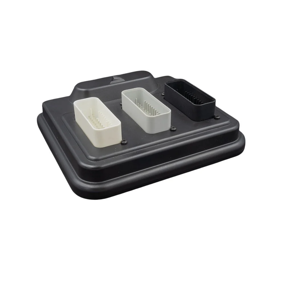
SCS Delta 900 ECU. Image: SCS Delta SXTune hardware reference; reproduced with permission.
SCS Delta 900 is a programmable SCS Delta engine-management controller. Delta 900 is a three-connector SCS ECU. The manufacturer's connector listing includes eight injector outputs, eight ignition outputs, dual throttle H-bridges, two sets of wideband lambda connections, knock inputs, two CAN channels and LIN. Confirm I/O allocation, output ratings and electrical features in the precise wiring document. SXTune 900 hardware reference.
Pinout and connector identification
B1–B2 and B3–B4 are throttle bridges 1 and 2. B9–B10 list injectors 7 and 8; B13–B16 list ignition 5–8. Connector C has separate sets of wideband connections C1–C5 and C13–C17, plus LIN at C8. The complete 900 connector pinout identifies every pin, its electrical description and the diagram. Numbering is model-specific; verify the connector view, supply fuses and the calibration. Adjacent models can use the same connector family with different functions.
Complete connector pin assignments
These assignments and electrical notes are from the SXTune delta900 technical reference. Application names are examples and some channels are configurable. Confirm the matching hardware revision, orientation, electrical limits and calibration in the source before wiring.
Connector A — AMPSeal 776164-1
PinNameDescriptionNotes1Battery DirectBattery Supply (15A fuse)Direct Battery Power 6-15V2IgnitionIgnition Switched Supply (10A fuse)Ignition Key Input3Power Ground 1Power GroundPower Ground4Low Side Output 13A Open CollectorInjector 15Low Side Output 23A Open CollectorInjector 26Low Side Output 33A Open CollectorInjector 37Low Side Output 43A Open CollectorInjector 48Crank/Cam GroundDigital GroundCrank/Cam Sensor Ground9Crank InputVR/Hall - Software SelectableCrank Sensor Input10Cam Input 1VR/Hall - Software SelectableInlet Cam Sensor 1 Input11NTC Input 13.16K pull-up to VREFCoolant Temp Input12NTC Input 23.16K pull-up to VREFAir Temp Input13Ignition 1TTL/Power Ignition OutputIgnition 114Ignition 2TTL/Power Ignition OutputIgnition 215Ignition 3TTL/Power Ignition OutputIgnition 316Ignition 4TTL/Power Ignition OutputIgnition 417Analog Input 147k pull-up to VREFUser Configurable 0-5V Analog Input18Cam Input 2VR/Hall - Software SelectableCam 2 / Wheel Speed19Analog Ground 1Analog GroundAnalog Ground20Lambda 1 InputWeak bias to 450mV0-5V Analog Input21CAN 1H120 Ohm TerminatedTo PC comms DB922CAN 1LTo PC comms DB923Low Side Output 53A Open Collector MFIOInjector 5 and Lambda 3 Input24Low Side Output 73A Open Collector w/ recirc diodeMain Relay/PWM125Low Side Output 83A Open Collector w/ recirc diodeFuel Pump Relay/PWM226Low Side Output 93A Open Collector w/ recirc diodePWM327Low Side Output 103A Open Collector w/ recirc diodePWM428Low Side Output 113A Open Collector with pull-up to VBATT via diodeTacho Output29Low Side Output 63A Open Collector MFIOInjector 6 and Lambda 4 Input30Analog Ground 2Analog GroundAnalog Ground31NTC Input 33.16K pull-up to VREFNTC132Analog Input 247k pull-up to VREFTPS133Analog Input 347k pull-up to VREFMAP34VREF500mA 5V supply to sensors5V Reference35Power Ground 2Power GroundPower Ground 2
Connector B — AMPSeal 776163-4
PinNameDescriptionNotesB1H Bridge 1 M+5A H-BridgeThrottle 1 +B2H Bridge 1 M-5A H-BridgeThrottle 1 -B3H Bridge 2 M+5A H-BridgeThrottle 2 +B4H Bridge 2 M-5A H-BridgeThrottle 2 -B5Bipolar Output 13A Hi Side/Lo Side DrivePWM5B6Bipolar Output 23A Hi Side/Lo Side DrivePWM6B7Bipolar Output 33A Hi Side/Lo Side DrivePWM7B8Bipolar Output 43A Hi Side/Lo Side DrivePWM8B9Low Side Output 123A Open CollectorInjector 7B10Low Side Output 133A Open CollectorInjector 8B11Cam Input 3VR/Hall - Software SelectableCam 3B12Cam Input 4VR/Hall - Software SelectableCam 4B13Ignition 5TTL/PowerShort circuit protection for PowerB14Ignition 6TTL/PowerShort circuit protection for PowerB15Ignition 7TTL/PowerShort circuit protection for PowerB16Ignition 8TTL/PowerShort circuit protection for PowerB17Hall Input 1Hall Effect InputWheel Speed LRB18Hall Input 2Hall Effect InputWheel Speed RRB19Hall Input 3Hall Effect InputWheel Speed LFB20Hall Input 4Hall Effect InputWheel Speed RFB21Knock 1 +B22Knock 2 +B23Knock GroundDigital GroundB24Lambda 2 InputWeak bias to 450mVLambda 2B25Analog Input 447k pull-up to VREFTPS2B26Analog Input 547k pull-up to VREFPPS1B27Analog Input 647k pull-up to VREFPPS2B28NTC Input 43.16k pull-up to VREFNTC2B29NTC Input 53.16k pull-up to VREFNTC3B30Analog Input 747k pull-up to VREFTPS3B31Analog Input 847k pull-up to VREFTPS4B32Analog Input 947k pull-up to VREFLinear 7B33Analog Input 1047k pull-up to VREFLinear 8B34CAN 2L120 Ohm TerminatedB35CAN 2H
Connector C — AMPSeal 776163-2
PinNameDescriptionNotesC1Wideband Lambda 1 Heater1.7A Open collector with recirc diode (LSU Pin 3)Wideband Lambda Sensor Heater OutputC2Wideband Lambda IpLSU Pin 1Wideband Lambda Sensor IpC3Wideband Lambda IaLSU Pin 5Wideband Lambda Sensor IaC4Wideband Lambda Virtual Ground (Vm)LSU Pin 2Wideband Lambda Sensor VmC5Wideband Lambda 1 Nernst (Un)LSU Pin 6Wideband Lambda Sensor UnC6Hall Input 6Cam Sensor 3 InputC7Hall Input 7Cam Sensor 4 InputC8LINC9L/S Output 140.75A Open collector with recirc diodeC10L/S Output 150.75A Open collector with recirc diodeC11VREF2200mA 5V supply to sensorsC12Analog Ground 2Analog GroundC13Wideband Lambda 2 Heater1.7A Open collector with recirc diode (LSU Pin 3)Wideband Lambda Sensor Heater OutputC14Wideband Lambda IpLSU Pin 1Wideband Lambda Sensor IpC15Wideband Lambda IaLSU Pin 5Wideband Lambda Sensor IaC16Wideband Lambda Virtual Ground (Vm)LSU Pin 2Wideband Lambda Sensor VmC17Wideband Lambda 2 Nernst (Un)LSU Pin 6Wideband Lambda Sensor UnC18Analog Input 1147k pull-up to VREFC19Analog Input 1247k pull-up to VREFC20Analog Input 1347k pull-up to VREFC21Low Side Output 161.5A Open collector with recirc diodeC22Low Side Output 171.5A Open collector with recirc diodeC23Low Side Output 181.5A Open collector with recirc diodeC24Low Side Output 191.5A Open collector with recirc diodeC25Low Side Output 201.7A Open collectorC26Low Side Output 211.7A Open collectorC27Low Side Output 22 (Relay Drive)0.75A Open collector with recirc diodeC28Low Side Output 23 (Relay Drive)0.75A Open collector with recirc diodeC29Low Side Output 24 (Relay Drive)0.75A Open collector with recirc diodeC30Low Side Output 25 (Relay Drive)0.75A Open collector with recirc diodeC31Low Side Output 26 (Relay Drive)0.75A Open collector with recirc diodeC32Hall Input 5Hall Effect Input (2k7 Pull-up to 5V)C33NTC Input 63.16k pull-up to VREFC34VREF3200mA 5V supply to sensorsC35Analog Ground 3Analog Ground
PC communications connectors
PinNameDescriptionNotesDB9-1GroundDB9-6CAN HighDB9-7CAN LowDB9-8Battery Voltage
Calibration and installation
Record hardware identity, firmware and the existing calibration. The SXTune documentation covers crank and cam setup, sensor configuration, electronic throttle, output testing, data logging and CAN. Capabilities depend on the exact unit and firmware; the presence of a menu in shared software does not establish hardware support. Match sensors, coil and injector drivers and fuse values to the original model documentation before applying power.
See SCS Delta family guide, the manufacturer legacy upgrade notes and the wiring index.
Rendered revisions
Open each version to inspect formatting, tables and photographs.
SCS Delta 900 is a programmable SCS Delta engine-management controller. Delta 900 is a three-connector SCS ECU. The manufacturer's connector listing includes eight injector outputs, eight ignition outputs, dual throttle H-bridges, two sets of wideband lambda connections, knock inputs, two CAN channels and LIN. Confirm I/O allocation, output ratings and electrical features in the precise wiring document. SXTune 900 hardware reference.
Pinout and connector identification
B1–B2 and B3–B4 are throttle bridges 1 and 2. B9–B10 list injectors 7 and 8; B13–B16 list ignition 5–8. Connector C has separate sets of wideband connections C1–C5 and C13–C17, plus LIN at C8. The complete 900 connector pinout identifies every pin, its electrical description and the diagram. Numbering is model-specific; verify the connector view, supply fuses and the calibration. Adjacent models can use the same connector family with different functions.
Complete connector pin assignments
These assignments and electrical notes are from the SXTune delta900 technical reference. Application names are examples and some channels are configurable. Confirm the matching hardware revision, orientation, electrical limits and calibration in the source before wiring.
Connector A — AMPSeal 776164-1
Pin
Name
Description
Notes
1
Battery Direct
Battery Supply (15A fuse)
Direct Battery Power 6-15V
2
Ignition
Ignition Switched Supply (10A fuse)
Ignition Key Input
3
Power Ground 1
Power Ground
Power Ground
4
Low Side Output 1
3A Open Collector
Injector 1
5
Low Side Output 2
3A Open Collector
Injector 2
6
Low Side Output 3
3A Open Collector
Injector 3
7
Low Side Output 4
3A Open Collector
Injector 4
8
Crank/Cam Ground
Digital Ground
Crank/Cam Sensor Ground
9
Crank Input
VR/Hall - Software Selectable
Crank Sensor Input
10
Cam Input 1
VR/Hall - Software Selectable
Inlet Cam Sensor 1 Input
11
NTC Input 1
3.16K pull-up to VREF
Coolant Temp Input
12
NTC Input 2
3.16K pull-up to VREF
Air Temp Input
13
Ignition 1
TTL/Power Ignition Output
Ignition 1
14
Ignition 2
TTL/Power Ignition Output
Ignition 2
15
Ignition 3
TTL/Power Ignition Output
Ignition 3
16
Ignition 4
TTL/Power Ignition Output
Ignition 4
17
Analog Input 1
47k pull-up to VREF
User Configurable 0-5V Analog Input
18
Cam Input 2
VR/Hall - Software Selectable
Cam 2 / Wheel Speed
19
Analog Ground 1
Analog Ground
Analog Ground
20
Lambda 1 Input
Weak bias to 450mV
0-5V Analog Input
21
CAN 1H
120 Ohm Terminated
To PC comms DB9
22
CAN 1L
To PC comms DB9
23
Low Side Output 5
3A Open Collector MFIO
Injector 5 and Lambda 3 Input
24
Low Side Output 7
3A Open Collector w/ recirc diode
Main Relay/PWM1
25
Low Side Output 8
3A Open Collector w/ recirc diode
Fuel Pump Relay/PWM2
26
Low Side Output 9
3A Open Collector w/ recirc diode
PWM3
27
Low Side Output 10
3A Open Collector w/ recirc diode
PWM4
28
Low Side Output 11
3A Open Collector with pull-up to VBATT via diode
Tacho Output
29
Low Side Output 6
3A Open Collector MFIO
Injector 6 and Lambda 4 Input
30
Analog Ground 2
Analog Ground
Analog Ground
31
NTC Input 3
3.16K pull-up to VREF
NTC1
32
Analog Input 2
47k pull-up to VREF
TPS1
33
Analog Input 3
47k pull-up to VREF
MAP
34
VREF
500mA 5V supply to sensors
5V Reference
35
Power Ground 2
Power Ground
Power Ground 2
Connector B — AMPSeal 776163-4
Pin
Name
Description
Notes
B1
H Bridge 1 M+
5A H-Bridge
Throttle 1 +
B2
H Bridge 1 M-
5A H-Bridge
Throttle 1 -
B3
H Bridge 2 M+
5A H-Bridge
Throttle 2 +
B4
H Bridge 2 M-
5A H-Bridge
Throttle 2 -
B5
Bipolar Output 1
3A Hi Side/Lo Side Drive
PWM5
B6
Bipolar Output 2
3A Hi Side/Lo Side Drive
PWM6
B7
Bipolar Output 3
3A Hi Side/Lo Side Drive
PWM7
B8
Bipolar Output 4
3A Hi Side/Lo Side Drive
PWM8
B9
Low Side Output 12
3A Open Collector
Injector 7
B10
Low Side Output 13
3A Open Collector
Injector 8
B11
Cam Input 3
VR/Hall - Software Selectable
Cam 3
B12
Cam Input 4
VR/Hall - Software Selectable
Cam 4
B13
Ignition 5
TTL/Power
Short circuit protection for Power
B14
Ignition 6
TTL/Power
Short circuit protection for Power
B15
Ignition 7
TTL/Power
Short circuit protection for Power
B16
Ignition 8
TTL/Power
Short circuit protection for Power
B17
Hall Input 1
Hall Effect Input
Wheel Speed LR
B18
Hall Input 2
Hall Effect Input
Wheel Speed RR
B19
Hall Input 3
Hall Effect Input
Wheel Speed LF
B20
Hall Input 4
Hall Effect Input
Wheel Speed RF
B21
Knock 1 +
B22
Knock 2 +
B23
Knock Ground
Digital Ground
B24
Lambda 2 Input
Weak bias to 450mV
Lambda 2
B25
Analog Input 4
47k pull-up to VREF
TPS2
B26
Analog Input 5
47k pull-up to VREF
PPS1
B27
Analog Input 6
47k pull-up to VREF
PPS2
B28
NTC Input 4
3.16k pull-up to VREF
NTC2
B29
NTC Input 5
3.16k pull-up to VREF
NTC3
B30
Analog Input 7
47k pull-up to VREF
TPS3
B31
Analog Input 8
47k pull-up to VREF
TPS4
B32
Analog Input 9
47k pull-up to VREF
Linear 7
B33
Analog Input 10
47k pull-up to VREF
Linear 8
B34
CAN 2L
120 Ohm Terminated
B35
CAN 2H
Connector C — AMPSeal 776163-2
Pin
Name
Description
Notes
C1
Wideband Lambda 1 Heater
1.7A Open collector with recirc diode (LSU Pin 3)
Wideband Lambda Sensor Heater Output
C2
Wideband Lambda Ip
LSU Pin 1
Wideband Lambda Sensor Ip
C3
Wideband Lambda Ia
LSU Pin 5
Wideband Lambda Sensor Ia
C4
Wideband Lambda Virtual Ground (Vm)
LSU Pin 2
Wideband Lambda Sensor Vm
C5
Wideband Lambda 1 Nernst (Un)
LSU Pin 6
Wideband Lambda Sensor Un
C6
Hall Input 6
Cam Sensor 3 Input
C7
Hall Input 7
Cam Sensor 4 Input
C8
LIN
C9
L/S Output 14
0.75A Open collector with recirc diode
C10
L/S Output 15
0.75A Open collector with recirc diode
C11
VREF2
200mA 5V supply to sensors
C12
Analog Ground 2
Analog Ground
C13
Wideband Lambda 2 Heater
1.7A Open collector with recirc diode (LSU Pin 3)
Wideband Lambda Sensor Heater Output
C14
Wideband Lambda Ip
LSU Pin 1
Wideband Lambda Sensor Ip
C15
Wideband Lambda Ia
LSU Pin 5
Wideband Lambda Sensor Ia
C16
Wideband Lambda Virtual Ground (Vm)
LSU Pin 2
Wideband Lambda Sensor Vm
C17
Wideband Lambda 2 Nernst (Un)
LSU Pin 6
Wideband Lambda Sensor Un
C18
Analog Input 11
47k pull-up to VREF
C19
Analog Input 12
47k pull-up to VREF
C20
Analog Input 13
47k pull-up to VREF
C21
Low Side Output 16
1.5A Open collector with recirc diode
C22
Low Side Output 17
1.5A Open collector with recirc diode
C23
Low Side Output 18
1.5A Open collector with recirc diode
C24
Low Side Output 19
1.5A Open collector with recirc diode
C25
Low Side Output 20
1.7A Open collector
C26
Low Side Output 21
1.7A Open collector
C27
Low Side Output 22 (Relay Drive)
0.75A Open collector with recirc diode
C28
Low Side Output 23 (Relay Drive)
0.75A Open collector with recirc diode
C29
Low Side Output 24 (Relay Drive)
0.75A Open collector with recirc diode
C30
Low Side Output 25 (Relay Drive)
0.75A Open collector with recirc diode
C31
Low Side Output 26 (Relay Drive)
0.75A Open collector with recirc diode
C32
Hall Input 5
Hall Effect Input (2k7 Pull-up to 5V)
C33
NTC Input 6
3.16k pull-up to VREF
C34
VREF3
200mA 5V supply to sensors
C35
Analog Ground 3
Analog Ground
PC communications connectors
Pin
Name
Description
Notes
DB9-1
Ground
DB9-6
CAN High
DB9-7
CAN Low
DB9-8
Battery Voltage
Calibration and installation
Record hardware identity, firmware and the existing calibration. The SXTune documentation covers crank and cam setup, sensor configuration, electronic throttle, output testing, data logging and CAN. Capabilities depend on the exact unit and firmware; the presence of a menu in shared software does not establish hardware support. Match sensors, coil and injector drivers and fuse values to the original model documentation before applying power.
SCS Delta 900 is a programmable SCS Delta engine-management controller. Delta 900 is a three-connector SCS ECU. The manufacturer's connector listing includes eight injector outputs, eight ignition outputs, dual throttle H-bridges, two sets of wideband lambda connections, knock inputs, two CAN channels and LIN. Confirm I/O allocation, output ratings and electrical features in the precise wiring document. SXTune 900 hardware reference.
Pinout and connector identification
B1–B2 and B3–B4 are throttle bridges 1 and 2. B9–B10 list injectors 7 and 8; B13–B16 list ignition 5–8. Connector C has separate sets of wideband connections C1–C5 and C13–C17, plus LIN at C8. The complete 900 connector pinout identifies every pin, its electrical description and the diagram. Numbering is model-specific; verify the connector view, supply fuses and the calibration. Adjacent models can use the same connector family with different functions.
Complete connector pin assignments
These assignments and electrical notes are from the SXTune delta900 technical reference. Application names are examples and some channels are configurable. Confirm the matching hardware revision, orientation, electrical limits and calibration in the source before wiring.
Connector A — AMPSeal 776164-1
Pin
Name
Description
Notes
1
Battery Direct
Battery Supply (15A fuse)
Direct Battery Power 6-15V
2
Ignition
Ignition Switched Supply (10A fuse)
Ignition Key Input
3
Power Ground 1
Power Ground
Power Ground
4
Low Side Output 1
3A Open Collector
Injector 1
5
Low Side Output 2
3A Open Collector
Injector 2
6
Low Side Output 3
3A Open Collector
Injector 3
7
Low Side Output 4
3A Open Collector
Injector 4
8
Crank/Cam Ground
Digital Ground
Crank/Cam Sensor Ground
9
Crank Input
VR/Hall - Software Selectable
Crank Sensor Input
10
Cam Input 1
VR/Hall - Software Selectable
Inlet Cam Sensor 1 Input
11
NTC Input 1
3.16K pull-up to VREF
Coolant Temp Input
12
NTC Input 2
3.16K pull-up to VREF
Air Temp Input
13
Ignition 1
TTL/Power Ignition Output
Ignition 1
14
Ignition 2
TTL/Power Ignition Output
Ignition 2
15
Ignition 3
TTL/Power Ignition Output
Ignition 3
16
Ignition 4
TTL/Power Ignition Output
Ignition 4
17
Analog Input 1
47k pull-up to VREF
User Configurable 0-5V Analog Input
18
Cam Input 2
VR/Hall - Software Selectable
Cam 2 / Wheel Speed
19
Analog Ground 1
Analog Ground
Analog Ground
20
Lambda 1 Input
Weak bias to 450mV
0-5V Analog Input
21
CAN 1H
120 Ohm Terminated
To PC comms DB9
22
CAN 1L
To PC comms DB9
23
Low Side Output 5
3A Open Collector MFIO
Injector 5 and Lambda 3 Input
24
Low Side Output 7
3A Open Collector w/ recirc diode
Main Relay/PWM1
25
Low Side Output 8
3A Open Collector w/ recirc diode
Fuel Pump Relay/PWM2
26
Low Side Output 9
3A Open Collector w/ recirc diode
PWM3
27
Low Side Output 10
3A Open Collector w/ recirc diode
PWM4
28
Low Side Output 11
3A Open Collector with pull-up to VBATT via diode
Tacho Output
29
Low Side Output 6
3A Open Collector MFIO
Injector 6 and Lambda 4 Input
30
Analog Ground 2
Analog Ground
Analog Ground
31
NTC Input 3
3.16K pull-up to VREF
NTC1
32
Analog Input 2
47k pull-up to VREF
TPS1
33
Analog Input 3
47k pull-up to VREF
MAP
34
VREF
500mA 5V supply to sensors
5V Reference
35
Power Ground 2
Power Ground
Power Ground 2
Connector B — AMPSeal 776163-4
Pin
Name
Description
Notes
B1
H Bridge 1 M+
5A H-Bridge
Throttle 1 +
B2
H Bridge 1 M-
5A H-Bridge
Throttle 1 -
B3
H Bridge 2 M+
5A H-Bridge
Throttle 2 +
B4
H Bridge 2 M-
5A H-Bridge
Throttle 2 -
B5
Bipolar Output 1
3A Hi Side/Lo Side Drive
PWM5
B6
Bipolar Output 2
3A Hi Side/Lo Side Drive
PWM6
B7
Bipolar Output 3
3A Hi Side/Lo Side Drive
PWM7
B8
Bipolar Output 4
3A Hi Side/Lo Side Drive
PWM8
B9
Low Side Output 12
3A Open Collector
Injector 7
B10
Low Side Output 13
3A Open Collector
Injector 8
B11
Cam Input 3
VR/Hall - Software Selectable
Cam 3
B12
Cam Input 4
VR/Hall - Software Selectable
Cam 4
B13
Ignition 5
TTL/Power
Short circuit protection for Power
B14
Ignition 6
TTL/Power
Short circuit protection for Power
B15
Ignition 7
TTL/Power
Short circuit protection for Power
B16
Ignition 8
TTL/Power
Short circuit protection for Power
B17
Hall Input 1
Hall Effect Input
Wheel Speed LR
B18
Hall Input 2
Hall Effect Input
Wheel Speed RR
B19
Hall Input 3
Hall Effect Input
Wheel Speed LF
B20
Hall Input 4
Hall Effect Input
Wheel Speed RF
B21
Knock 1 +
B22
Knock 2 +
B23
Knock Ground
Digital Ground
B24
Lambda 2 Input
Weak bias to 450mV
Lambda 2
B25
Analog Input 4
47k pull-up to VREF
TPS2
B26
Analog Input 5
47k pull-up to VREF
PPS1
B27
Analog Input 6
47k pull-up to VREF
PPS2
B28
NTC Input 4
3.16k pull-up to VREF
NTC2
B29
NTC Input 5
3.16k pull-up to VREF
NTC3
B30
Analog Input 7
47k pull-up to VREF
TPS3
B31
Analog Input 8
47k pull-up to VREF
TPS4
B32
Analog Input 9
47k pull-up to VREF
Linear 7
B33
Analog Input 10
47k pull-up to VREF
Linear 8
B34
CAN 2L
120 Ohm Terminated
B35
CAN 2H
Connector C — AMPSeal 776163-2
Pin
Name
Description
Notes
C1
Wideband Lambda 1 Heater
1.7A Open collector with recirc diode (LSU Pin 3)
Wideband Lambda Sensor Heater Output
C2
Wideband Lambda Ip
LSU Pin 1
Wideband Lambda Sensor Ip
C3
Wideband Lambda Ia
LSU Pin 5
Wideband Lambda Sensor Ia
C4
Wideband Lambda Virtual Ground (Vm)
LSU Pin 2
Wideband Lambda Sensor Vm
C5
Wideband Lambda 1 Nernst (Un)
LSU Pin 6
Wideband Lambda Sensor Un
C6
Hall Input 6
Cam Sensor 3 Input
C7
Hall Input 7
Cam Sensor 4 Input
C8
LIN
C9
L/S Output 14
0.75A Open collector with recirc diode
C10
L/S Output 15
0.75A Open collector with recirc diode
C11
VREF2
200mA 5V supply to sensors
C12
Analog Ground 2
Analog Ground
C13
Wideband Lambda 2 Heater
1.7A Open collector with recirc diode (LSU Pin 3)
Wideband Lambda Sensor Heater Output
C14
Wideband Lambda Ip
LSU Pin 1
Wideband Lambda Sensor Ip
C15
Wideband Lambda Ia
LSU Pin 5
Wideband Lambda Sensor Ia
C16
Wideband Lambda Virtual Ground (Vm)
LSU Pin 2
Wideband Lambda Sensor Vm
C17
Wideband Lambda 2 Nernst (Un)
LSU Pin 6
Wideband Lambda Sensor Un
C18
Analog Input 11
47k pull-up to VREF
C19
Analog Input 12
47k pull-up to VREF
C20
Analog Input 13
47k pull-up to VREF
C21
Low Side Output 16
1.5A Open collector with recirc diode
C22
Low Side Output 17
1.5A Open collector with recirc diode
C23
Low Side Output 18
1.5A Open collector with recirc diode
C24
Low Side Output 19
1.5A Open collector with recirc diode
C25
Low Side Output 20
1.7A Open collector
C26
Low Side Output 21
1.7A Open collector
C27
Low Side Output 22 (Relay Drive)
0.75A Open collector with recirc diode
C28
Low Side Output 23 (Relay Drive)
0.75A Open collector with recirc diode
C29
Low Side Output 24 (Relay Drive)
0.75A Open collector with recirc diode
C30
Low Side Output 25 (Relay Drive)
0.75A Open collector with recirc diode
C31
Low Side Output 26 (Relay Drive)
0.75A Open collector with recirc diode
C32
Hall Input 5
Hall Effect Input (2k7 Pull-up to 5V)
C33
NTC Input 6
3.16k pull-up to VREF
C34
VREF3
200mA 5V supply to sensors
C35
Analog Ground 3
Analog Ground
PC communications connectors
Pin
Name
Description
Notes
DB9-1
Ground
DB9-6
CAN High
DB9-7
CAN Low
DB9-8
Battery Voltage
Calibration and installation
Record hardware identity, firmware and the existing calibration. The SXTune documentation covers crank and cam setup, sensor configuration, electronic throttle, output testing, data logging and CAN. Capabilities depend on the exact unit and firmware; the presence of a menu in shared software does not establish hardware support. Match sensors, coil and injector drivers and fuse values to the original model documentation before applying power.