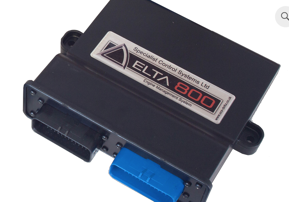
SCS Delta 800 is a programmable SCS Delta engine-management controller. Legacy SCS Delta controller documented with two AMPSeal connectors A 776164-1 and B 776163-4 plus female DB9 CAN connector. The manufacturer pinout shows two H-bridge throttle motor pairs and positions for eight injector and eight ignition outputs, subject to software configuration and output ratings. SXTune 800 hardware reference.
Pinout and connector identification
A1 battery, A2 switched ignition, A3 power ground, A4–A7 injector 1–4, A9 crank and A10 cam 1. On B, B1–B4 are the two H-bridge throttle motor pairs; B9–B10 are injector 7–8 and B13–B16 ignition 5–8. The complete 800 connector pinout identifies every pin, its electrical description and the diagram. Numbering is model-specific; verify the connector view, supply fuses and the calibration. Adjacent models can use the same connector family with different functions.
Complete connector pin assignments
These assignments and electrical notes are from the SXTune delta800 technical reference. Application names are examples and some channels are configurable. Confirm the matching hardware revision, orientation, electrical limits and calibration in the source before wiring.
Connector A
| Pin | Name | Description | Notes |
|---|---|---|---|
| 1 | Battery | Direct Battery Supply (15A fuse) | Direct Battery Power 6-15V |
| 2 | Ignition | Ignition Switched Supply (10A fuse) | Ignition Key Input |
| 3 | Power Ground 1 | Power Ground | Power Ground 1 |
| 4 | Low Side Output 1 | 3A Open Collector | Injector 1 Output |
| 5 | Low Side Output 2 | 3A Open Collector | Injector 2 Output |
| 6 | Low Side Output 3 | 3A Open Collector | Injector 3 Output |
| 7 | Low Side Output 4 | 3A Open Collector | Injector 4 Output |
| 8 | Crank/Cam Ground | Digital Ground | Crank/Cam Sensor Ground |
| 9 | Crank Input | VR/Hall - Software Selectable | Crank Sensor Input |
| 10 | Cam Input 1 | VR/Hall - Software Selectable | Cam Sensor 1 Input |
| 11 | NTC Input 1 | 3.16K pull-up to VREF | Coolant Temperature Input |
| 12 | NTC Input 2 | 3.16K pull-up to VREF | Air Temperature Input |
| 13 | Ignition 1 | TTL/Power Ignition Output | Software Configurable Output |
| 14 | Ignition 2 | TTL/Power Ignition Output | Software Configurable Output |
| 15 | Ignition 3 | TTL/Power Ignition Output | Software Configurable Output |
| 16 | Ignition 4 | TTL/Power Ignition Output | Software Configurable Output |
| 17 | Analog Input 1 | 47k pull-up to VREF | Linear 1 Input |
| 18 | Cam Input 2 | VR/Hall - Software Selectable | Cam Sensor 2 Input |
| 19 | Analog Ground 1 | Analog Ground | Analog Ground |
| 20 | Lambda 1 Input | Weak bias to 450mV | Lambda Sensor 2 Input |
| 21 | CAN 1H | 120 Ohm Terminated | To PC comms DB9 |
| 22 | CAN 1L | To PC comms DB9 | |
| 23 | Low Side Output 5 | 3A Open Collector | Auxiliary 1 / Injector 5 Output |
| 24 | Low Side Output 7 | 3A Open Collector w/ recirc diode | Main Relay/PWM1 |
| 25 | Low Side Output 8 | 3A Open Collector w/ recirc diode | Fuel Pump Relay/PWM2 |
| 26 | Low Side Output 9 | 3A Open Collector w/ recirc diode | PWM3 Output |
| 27 | Low Side Output 10 | 3A Open Collector w/ recirc diode | PWM4 Output |
| 28 | Low Side Output 11 | 3A Open Collector with pull-up to VBATT via diode | Tachometer Output |
| 29 | Low Side Output 6 | 3A Open Collector | Auxiliary 2 / Injector 6 Output |
| 30 | Analog Ground 2 | Analog Ground | Analog Sensors Ground |
| 31 | NTC Input 3 | 3.16K pull-up to VREF | NTC1 Input |
| 32 | Analog Input 2 | 47k pull-up to VREF | Throttle Position Sensor Input |
| 33 | Analog Input 3 | 47k pull-up to VREF | Manifold Pressure Sensor Input |
| 34 | VREF | 500mA 5V supply to sensors | 5V Reference Sensor Supply |
| 35 | Power Ground 2 | Power Ground | Power Ground 2 |
Connector B
| Pin | Name | Description | Notes |
|---|---|---|---|
| B1 | H Bridge 1 M+ | 5A H-Bridge | Throttle Motor 1 + |
| B2 | H Bridge 1 M- | 5A H-Bridge | Throttle Motor 1 - |
| B3 | H Bridge 2 M+ | 5A H-Bridge | Throttle Motor 2 + |
| B4 | H Bridge 2 M- | 5A H-Bridge | Throttle Motor 2 - |
| B5 | Bipolar Output 1 | 3A Hi Side/Lo Side Drive | PWM5 Output |
| B6 | Bipolar Output 2 | 3A Hi Side/Lo Side Drive | PWM6 Output |
| B7 | Bipolar Output 3 | 3A Hi Side/Lo Side Drive | PWM7 Output |
| B8 | Bipolar Output 4 | 3A Hi Side/Lo Side Drive | PWM8 Output |
| B9 | Low Side Output 12 | 3A Open Collector | Injector 7 Output |
| B10 | Low Side Output 13 | 3A Open Collector | Injector 8 Output |
| B11 | Cam Input 3 | VR/Hall - Software Selectable | Cam Sensor 3 Input |
| B12 | Cam Input 4 | VR/Hall - Software Selectable | Cam Sensor 4 Input |
| B13 | Ignition 5 | TTL/Power | Software Configurable Output |
| B14 | Ignition 6 | TTL/Power | Software Configurable Output |
| B15 | Ignition 7 | TTL/Power | Short circuit protection for Power |
| B16 | Ignition 8 | TTL/Power | Short circuit protection for Power |
| B17 | Hall Input 1 | Hall Effect Input | Wheel Speed LR |
| B18 | Hall Input 2 | Hall Effect Input | Wheel Speed RR |
| B19 | Hall Input 3 | Hall Effect Input | Wheel Speed LF |
| B20 | Hall Input 4 | Hall Effect Input | Wheel Speed RF |
| B21 | Knock 1 + | Knock 1 Signal Input | |
| B22 | Knock 2 + | Knock 2 Signal Input | |
| B23 | Knock Ground | Digital Ground | |
| B24 | Lambda 2 Input | Weak bias to 450mV | Lambda 2 |
| B25 | Analog Input 4 | 47k pull-up to VREF | TPS2 |
| B26 | Analog Input 5 | 47k pull-up to VREF | PPS1 |
| B27 | Analog Input 6 | 47k pull-up to VREF | PPS2 |
| B28 | NTC Input 4 | 3.16k pull-up to VREF | NTC2 Input |
| B29 | NTC Input 5 | 3.16k pull-up to VREF | NTC3 Input |
| B30 | Analog Input 7 | 47k pull-up to VREF | Linear 5 Input |
| B31 | Analog Input 8 | 47k pull-up to VREF | Linear 6 Input |
| B32 | Analog Input 9 | 47k pull-up to VREF | Linear 7 Input |
| B33 | Analog Input 10 | 47k pull-up to VREF | Linear 8 Input |
| B34 | CAN 2L | CAN 2 Low | 120 Ohm Terminated |
| B35 | CAN 2H | CAN 2 High |
PC communications DB9 female
| Pin | Name |
|---|---|
| 1 | Ground |
| 6 | CAN High |
| 7 | CAN Low |
| 8 | Battery Voltage |
PC communications DTM
| Pin | Name |
|---|---|
| 1 | Battery Voltage |
| 2 | Ground |
| 3 | CAN High |
| 4 | CAN Low |
Calibration and installation
Record hardware identity, firmware and the existing calibration. The SXTune documentation covers crank and cam setup, sensor configuration, electronic throttle, output testing, data logging and CAN. Capabilities depend on the exact unit and firmware; the presence of a menu in shared software does not establish hardware support. Match sensors, coil and injector drivers and fuse values to the original model documentation before applying power.
See SCS Delta family guide, the manufacturer legacy upgrade notes and the wiring index.