Removed text is struck through; added text is highlighted.
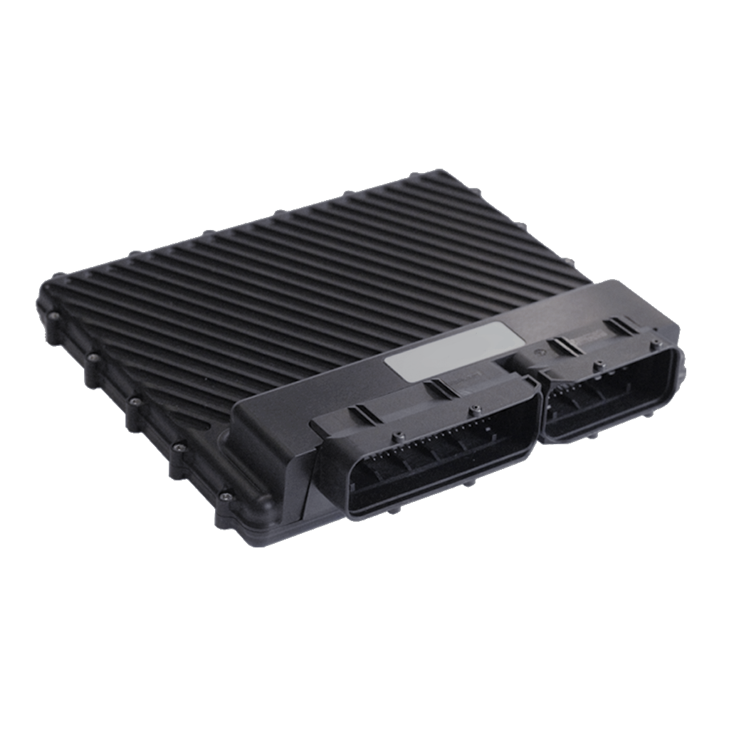
Syvecs S12 standalone ECU shown as a family illustration. This vehicle-specific kit and its adapter or wiring are not pictured and may differ. Image: Syvecs, reproduced with permission.
Model and vehicle application
Syvecs lists this vehicle-specific standalone or plug-in ECU kit as Lamborghini Gallardo LP560 S12, with product code S12-LAM560. The product page and its stated vehicle, model and transmission details define this particular application; confirm market, model year, engine, ECU connector and transmission against Syvecs before ordering.
This entry describes the dedicated vehicle kit. It is distinct from the generic wire-in ECU: a plug-in kit can use application-specific adaptor wiring, a carrier, additional modules and an application calibration. The listed hardware or supported equipment can vary by revision.
Wiring and pinout
Syvecs Lamborghini Gallardo LP560 S12 installation and wiring document. Follow the connector orientation, application-specific tables, installation notes and hardware revision in this document. Do not transfer assignments from another vehicle merely because the underlying ECU family is similar. The link was checked to return a PDF.
For other variants and manual revisions consult the manufacturer's vehicle-specific manual index. Available spare inputs and outputs can be used only within their electrical limits and with a matching calibration.
Calibration and service
Use the correct Syvecs software, firmware and base calibration for the exact vehicle and installed hardware. The Syvecs software portal and firmware archive provide manufacturer support. A base map is a starting point and needs checking against the actual engine, injectors, sensors and modifications.
Sources
Syvecs Lamborghini Gallardo LP560 S12 product listing and applicationManufacturer kit installation and pinout manualSyvecs plug-in kit support index
R8 / LP560 kit S12 pin scheduleThe Syvecs R8 / LP560 kit manual gives the following 121 S12 pin entries for its documented kit. The source combines ECU labels, SCal names and loom descriptions; fields are retained together, with its spelling and shared/configurable functions. It is a kit-specific schedule, not a general R8 factory ECU pinout; confirm engine, loom and ECU revision with Syvecs. Use the original for electrical ratings and connector orientation.S12 pinManufacturer signal and application notes1PWRGND | Ecu Ground | Ground2IGN1 | Ignition (20A Open Collector) | IGN13IGN2 | Ignition (20A Open Collector) | IGN24IGN3 | Ignition (20A Open Collector) | IGN35IGN4 | Ignition (20A Open Collector) | IGN46IN25 | FUEL PRESSURE DI 27KNOCK4 | Knock Sensor 2 | Knock 48KNOCKGND | KNOCK GROUND9THERMO2 +10IN21 | Thermistor Input | AIR TEMP11IN18 | 5V Analogue Input | INTAKE MANIFOLD FLAP POT12IN14 | Configurable Analogue Input | FUEL PRESSURE LOW PRESSURE13IN11 | Configurable Analogue Input | TPS1A14IN7 | Configurable Analogue Input | TPS1B15IN4 | Configurable Analogue Input | External - MAP Sensor16IN1 | Configurable Analogue Input | CRUISE CONTROL17LAMI 1 | Red LSU18CAN LO 219RS232 TX20LAN RX- | Orange/White21FUEL 7 | Fuel Injector (10A Open Collector) | 12 Way DTM for Extra Injectors22FUEL 3 | Fuel Injector (10A Open Collector) | 12 Way DTM for Extra Injectors23VBAT | Main 12v24PWRGND | Ground25IN26 | 5V Analogue Input | PPS2265V OUT | 5V OUT | 5V Out27KNK1 | KNOCK1 | KNOCK128THERO 1 - | THERO 1 -29IN22 | Thermistor Input | External – Air Charge Temp30IN19 | 5V | PPS131IN15 | Configurable Analogue Input | INTAKE MANIFOLD FLAP POT 232IN12 | Configurable Analogue Input | TPS2A33IN08 | Configurable Analogue Input | TPS2B34ANGND | SENSOR GROUND | Custom Loom for Map Sensor35IN02 | Configurable Analogue Input | Brake Servo Pressure36LAMV 1 | Black LSU37CAN HI 338RS232 RX39LAN RX+ | White/Orange40OUT8 | 12 Way DTM for Extra Injectors41OUT4 | 12 Way DTM for Extra Injectors42VBAT | Bank 1 and Bank 2 T14H connector pin 14 and custom loom for boost solenoid 12 V43PWRGND | Relay and canbridge ground44IN27 | 5V | FUEL PRESSURE DI455V OUT | TPS 5V,46KNOCK2 | Knock247THERMO1+48IN23 | Thermistor Input | ENGINE COOLANT TEMP49IN20 | 5V | Steering Column Crank Signal50IN16 | Configurable Analogue Input51ANGND52IN09 | Configurable Analogue Input | Crank Signal53IN05 | Configurable Analogue Input54ANGND | T60 -28 | OIL TEMP, LOW FUEL PRESSURE, PPS55LAMV256CAN LO 357COMGND58CAN HI 1 | To Can Bridge X1 - Pin359LAN TX- | Green/White60OUT5 | VVT1 EXHAUST61OUT1 | VVT1 INLET62HBRIDGE563IN28 | 5V | BRAKE SIGNAL6410VOUT65KNOCK 3 | Knock366THEMO 02 -67IN24 | Thermistor Input | ENGINE OIL TEMP68ANGND | CRANK SIG, TPS GROUNDS69IN17 | 5V | Park/Neutral Input from TCM70IN13 | Cam In171IN10 | Configurable Analogue Input | Cam ex172IN6 | Configurable Analogue Input | Cam In273IN3 | Configurable Analogue Input | Cam ex274LAMI 275LamGND | Yellow LSU76CAN HI 0277CAN LO 1 | To Can Bridge X1 - Pin278LAN TX+ | White/Green79OUT6 | 12 Way DTM for Extra Injectors80OUT2 | 12 Way DTM for Extra Injectors81H BRIDGE 6 | Custom Loom for Boost Solenoid82H BRIDGE 1 | DBW 1 +83PWM4 | FUEL PUMPS84PWM8 | Brake Servo Relay85FUEL12 | 12 Way DTM for Extra Injectors86FUEL16 | 12 Way DTM for Extra Injectors87FUEL20 | VVT2 EXHAUST88FUEL24 | VVT2 INLET89VBAT | Main 12v90H BRIDGE 2 | DBW1 -91PWM3 | EXHAUST FLAPS92PWM7 | AUTOGEARBOX/PWRSTEERING SIGNAL93FUEL11 | 12 Way DTM for Extra Injectors94FUEL15 | 12 Way DTM for Extra Injectors95FUEL19 | INJECTOR 1 SIG96FUEL23 | INJECTOR 2 SIG97PWRGND98H BRIDGE 3 | DBW 2 +99PWM2 | Fan1 & 2 Signal100PWM6 | INTAKE MANIFOLD FLAP101FUEL10 | INJECTOR 3 SIG102FUEL14 | INJECTOR 4 SIG103FUEL18 | INJECTOR 5 SIG104FUEL22 | INJECTOR 6 SIG105PWRGND106HBRIDGE4 | DBW2 -107PWM1 | STARTER MOTOR RELAY108PWM5 | LAMBDA HEATERS109FUEL9 | INJECTOR 7 SIG110FUEL13 | INJECTOR 8 SIG111FUEL17 | INJECTOR 9 SIG112FUEL21 | INJECTOR 10 SIG113PWRGND114IGN5 | IGN5115IGN6 | IGN6116IGN7 | IGN7117IGN8 | IGN8118IGN9 | IGN9119IGN10 | IGN10120IGN11 | DI Spill Valve1121IGN12 | Di Spill Valve2Additional injector 12-way DTMThe same manual supplies this additional-injector breakout connector. It states that its two injector looms must connect to the black connectors, not the brown connectors.DTM terminalFunction1Fuel output 72Fuel output 33Fuel output 84Fuel output 45Fuel output 66Fuel output 27Fuel output 128Fuel output 169Fuel output 1110Fuel output 1511VBatt 12 V12VBatt 12 V
Rendered revisions
Open each version to inspect formatting, tables and photographs.
Syvecs lists this vehicle-specific standalone or plug-in ECU kit as Lamborghini Gallardo LP560 S12, with product code S12-LAM560. The product page and its stated vehicle, model and transmission details define this particular application; confirm market, model year, engine, ECU connector and transmission against Syvecs before ordering.
This entry describes the dedicated vehicle kit. It is distinct from the generic wire-in ECU: a plug-in kit can use application-specific adaptor wiring, a carrier, additional modules and an application calibration. The listed hardware or supported equipment can vary by revision.
Wiring and pinout
Syvecs Lamborghini Gallardo LP560 S12 installation and wiring document. Follow the connector orientation, application-specific tables, installation notes and hardware revision in this document. Do not transfer assignments from another vehicle merely because the underlying ECU family is similar. The link was checked to return a PDF.
For other variants and manual revisions consult the manufacturer's vehicle-specific manual index. Available spare inputs and outputs can be used only within their electrical limits and with a matching calibration.
Calibration and service
Use the correct Syvecs software, firmware and base calibration for the exact vehicle and installed hardware. The Syvecs software portal and firmware archive provide manufacturer support. A base map is a starting point and needs checking against the actual engine, injectors, sensors and modifications.
Revision 3: Syvecs Lamborghini Gallardo LP560 S12 Plug-in ECUSyvecs S12 standalone ECU shown as a family illustration. This vehicle-specific kit and its adapter or wiring are not pictured and may differ. Image: Syvecs, reproduced with permission.
Model and vehicle application
Syvecs lists this vehicle-specific standalone or plug-in ECU kit as Lamborghini Gallardo LP560 S12, with product code S12-LAM560. The product page and its stated vehicle, model and transmission details define this particular application; confirm market, model year, engine, ECU connector and transmission against Syvecs before ordering.
This entry describes the dedicated vehicle kit. It is distinct from the generic wire-in ECU: a plug-in kit can use application-specific adaptor wiring, a carrier, additional modules and an application calibration. The listed hardware or supported equipment can vary by revision.
Wiring and pinout
Syvecs Lamborghini Gallardo LP560 S12 installation and wiring document. Follow the connector orientation, application-specific tables, installation notes and hardware revision in this document. Do not transfer assignments from another vehicle merely because the underlying ECU family is similar. The link was checked to return a PDF.
For other variants and manual revisions consult the manufacturer's vehicle-specific manual index. Available spare inputs and outputs can be used only within their electrical limits and with a matching calibration.
Calibration and service
Use the correct Syvecs software, firmware and base calibration for the exact vehicle and installed hardware. The Syvecs software portal and firmware archive provide manufacturer support. A base map is a starting point and needs checking against the actual engine, injectors, sensors and modifications.
The Syvecs R8 / LP560 kit manual gives the following 121 S12 pin entries for its documented kit. The source combines ECU labels, SCal names and loom descriptions; fields are retained together, with its spelling and shared/configurable functions. It is a kit-specific schedule, not a general R8 factory ECU pinout; confirm engine, loom and ECU revision with Syvecs. Use the original for electrical ratings and connector orientation.
S12 pin
Manufacturer signal and application notes
1
PWRGND | Ecu Ground | Ground
2
IGN1 | Ignition (20A Open Collector) | IGN1
3
IGN2 | Ignition (20A Open Collector) | IGN2
4
IGN3 | Ignition (20A Open Collector) | IGN3
5
IGN4 | Ignition (20A Open Collector) | IGN4
6
IN25 | FUEL PRESSURE DI 2
7
KNOCK4 | Knock Sensor 2 | Knock 4
8
KNOCKGND | KNOCK GROUND
9
THERMO2 +
10
IN21 | Thermistor Input | AIR TEMP
11
IN18 | 5V Analogue Input | INTAKE MANIFOLD FLAP POT
The same manual supplies this additional-injector breakout connector. It states that its two injector looms must connect to the black connectors, not the brown connectors.