Removed text is struck through; added text is highlighted.
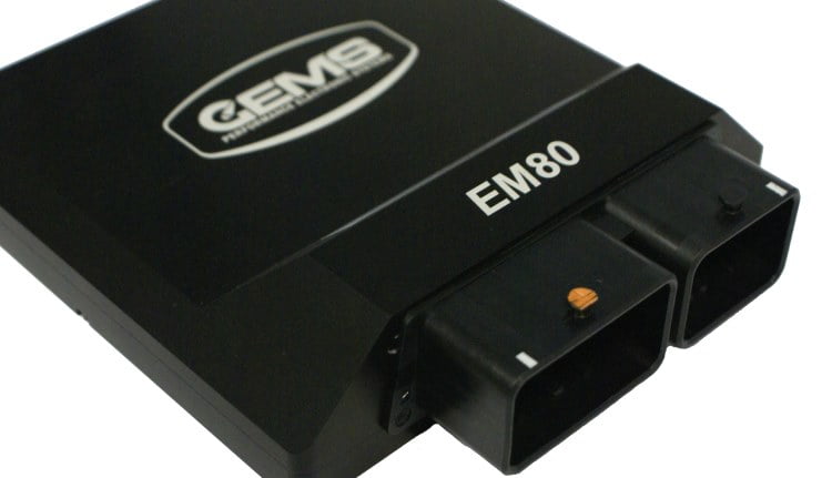
EM80-M product page uses an EM80 family illustration. Source: GEMS Performance Electronics; used with permission.
GEMS EM80-M: A model-based-control derivative of EM80, supplied with engine-management code or a reduced base platform. Manufacturer source.
Hardware and control
GEMS describes user-generated Simulink control, GWv4 calibration, eight ignition and eight peak-and-hold injector drivers, two CAN buses, Ethernet and 256 MB logging. Its product page and technical sheet differ on the stated count of analogue inputs; check the actual configuration and shared inputs. GEMS model information.
GEMS systems use GWv4 configuration, with the required ECU definition and licence; software options and custom builds can differ. Record the label, hardware and firmware and confirm connected devices against the matching documentation. GWv4 manual.
Connector 1 pinout — 103937 rev 6
The manufacturer technical specification identifies connector 1 as the 32-position mating connector; use its drawing and cavity markings for orientation, verify current limits and shared input functions. These positions apply only to this specific model and document revision.
Connector 2 pinout — 103937 rev 6The GEMS EM80-M rev 6 datasheet identifies the 48-position connector. The EM80-M and EM80 datasheets assign different coil-driver names at L2, M2 and M3: check the exact model and software before wiring. Consult the original for codes, orientation and electrical notes.PinFunction in sourceA1PWM driver 3B1PWM driver 4C1Fuel injector driver 1D1Fuel injector driver 2E1Fuel injector driver 3F1Fuel injector driver 4G1Fuel injector driver 5H1Fuel injector driver 6J1Fuel injector driver 7K1Fuel injector driver 8L1Main 12 V supplyM1Power returnA25 V sensor supply 3B2Timing input 12C2Timing input 11D2Timing input 10E2Timing input 9F2Timing groundG2Wideband lambda 1H2Wideband lambda 2J2Wideband lambda 3K2Wideband lambda 4L2Ignition coil driver 4M2Ignition coil driver 3A3Sensor groundB3Air inlet temperature inputC3Accelerator pedal input 1D3Accelerator pedal input 2E3Timing input 1F3Timing input 2G3Timing input 3H3Timing input 4J35 V sensor supply 2K3Wideband lambda heaterL3Bridge driver B−M3Ignition coil driver 2A4PWM driver 7B4PWM driver 8C4PWM low-side driver 15D4PWM low-side driver 16E4PWM low-side driver 14F4PWM low-side driver 13G4PWM low-side driver 12H4PWM low-side driver 11J4PWM low-side driver 10K4PWM low-side driver 9L4Bridge driver B+M4Ignition coil driver 1Some functions can be reassigned or shared; match the actual hardware and calibration.The 48-way connector 2, complete electrical notes and drawings remain in the linked original. Some functions can be reassigned or shared; match the actual hardware and calibration.
Further references
GEMS EM80-M manufacturer sourceModel-specific technical and wiring specificationGEMS software and downloadsGEMS manufacturer overview
Sources reviewed 17 November 2026.
Rendered revisions
Open each version to inspect formatting, tables and photographs.
Revision 1: GEMS EM80-MEM80-M product page uses an EM80 family illustration. Source: GEMS Performance Electronics; used with permission.
GEMS EM80-M: A model-based-control derivative of EM80, supplied with engine-management code or a reduced base platform. Manufacturer source.
Hardware and control
GEMS describes user-generated Simulink control, GWv4 calibration, eight ignition and eight peak-and-hold injector drivers, two CAN buses, Ethernet and 256 MB logging. Its product page and technical sheet differ on the stated count of analogue inputs; check the actual configuration and shared inputs. GEMS model information.
GEMS systems use GWv4 configuration, with the required ECU definition and licence; software options and custom builds can differ. Record the label, hardware and firmware and confirm connected devices against the matching documentation. GWv4 manual.
Connector 1 pinout — 103937 rev 6
The manufacturer technical specification identifies connector 1 as the 32-position mating connector; use its drawing and cavity markings for orientation, verify current limits and shared input functions. These positions apply only to this specific model and document revision.
Pin
Function in source
A1
Knock input +
B1
Knock input −
C1
Active throttle feedback 2
D1
Active throttle feedback 1
E1
MAF input
F1
Coolant temperature input
G1
Bridge driver A+
H1
Ignition coil driver 8
A2
CAN 2 low
B2
CAN 2 high
C2
Active throttle feedback 3
D2
Active throttle feedback 4
E2
5 V sensor supply 1
F2
Sensor ground
G2
Bridge driver A−
H2
Ignition coil driver 7
A3
CAN 1 low
B3
CAN 1 high
C3
MAP input
D3
Lambda input 1, narrowband
E3
Lambda input 2, narrowband
F3
Sensor ground
G3
Ignition coil driver 6
H3
Ignition coil driver 5
A4
Ethernet RX−
B4
Ethernet RX+
C4
Ethernet TX−
D4
Ethernet TX+
E4
Differential analogue input −
F4
Differential analogue input +
G4
Secondary 12 V supply / ignition switch
H4
Power return
The 48-way connector 2, complete electrical notes and drawings remain in the linked original. Some functions can be reassigned or shared; match the actual hardware and calibration.
Revision 2: GEMS EM80-MEM80-M product page uses an EM80 family illustration. Source: GEMS Performance Electronics; used with permission.
GEMS EM80-M: A model-based-control derivative of EM80, supplied with engine-management code or a reduced base platform. Manufacturer source.
Hardware and control
GEMS describes user-generated Simulink control, GWv4 calibration, eight ignition and eight peak-and-hold injector drivers, two CAN buses, Ethernet and 256 MB logging. Its product page and technical sheet differ on the stated count of analogue inputs; check the actual configuration and shared inputs. GEMS model information.
GEMS systems use GWv4 configuration, with the required ECU definition and licence; software options and custom builds can differ. Record the label, hardware and firmware and confirm connected devices against the matching documentation. GWv4 manual.
Connector 1 pinout — 103937 rev 6
The manufacturer technical specification identifies connector 1 as the 32-position mating connector; use its drawing and cavity markings for orientation, verify current limits and shared input functions. These positions apply only to this specific model and document revision.
Pin
Function in source
A1
Knock input +
B1
Knock input −
C1
Active throttle feedback 2
D1
Active throttle feedback 1
E1
MAF input
F1
Coolant temperature input
G1
Bridge driver A+
H1
Ignition coil driver 8
A2
CAN 2 low
B2
CAN 2 high
C2
Active throttle feedback 3
D2
Active throttle feedback 4
E2
5 V sensor supply 1
F2
Sensor ground
G2
Bridge driver A−
H2
Ignition coil driver 7
A3
CAN 1 low
B3
CAN 1 high
C3
MAP input
D3
Lambda input 1, narrowband
E3
Lambda input 2, narrowband
F3
Sensor ground
G3
Ignition coil driver 6
H3
Ignition coil driver 5
A4
Ethernet RX−
B4
Ethernet RX+
C4
Ethernet TX−
D4
Ethernet TX+
E4
Differential analogue input −
F4
Differential analogue input +
G4
Secondary 12 V supply / ignition switch
H4
Power return
Connector 2 pinout — 103937 rev 6
The GEMS EM80-M rev 6 datasheet identifies the 48-position connector. The EM80-M and EM80 datasheets assign different coil-driver names at L2, M2 and M3: check the exact model and software before wiring. Consult the original for codes, orientation and electrical notes.
Pin
Function in source
A1
PWM driver 3
B1
PWM driver 4
C1
Fuel injector driver 1
D1
Fuel injector driver 2
E1
Fuel injector driver 3
F1
Fuel injector driver 4
G1
Fuel injector driver 5
H1
Fuel injector driver 6
J1
Fuel injector driver 7
K1
Fuel injector driver 8
L1
Main 12 V supply
M1
Power return
A2
5 V sensor supply 3
B2
Timing input 12
C2
Timing input 11
D2
Timing input 10
E2
Timing input 9
F2
Timing ground
G2
Wideband lambda 1
H2
Wideband lambda 2
J2
Wideband lambda 3
K2
Wideband lambda 4
L2
Ignition coil driver 4
M2
Ignition coil driver 3
A3
Sensor ground
B3
Air inlet temperature input
C3
Accelerator pedal input 1
D3
Accelerator pedal input 2
E3
Timing input 1
F3
Timing input 2
G3
Timing input 3
H3
Timing input 4
J3
5 V sensor supply 2
K3
Wideband lambda heater
L3
Bridge driver B−
M3
Ignition coil driver 2
A4
PWM driver 7
B4
PWM driver 8
C4
PWM low-side driver 15
D4
PWM low-side driver 16
E4
PWM low-side driver 14
F4
PWM low-side driver 13
G4
PWM low-side driver 12
H4
PWM low-side driver 11
J4
PWM low-side driver 10
K4
PWM low-side driver 9
L4
Bridge driver B+
M4
Ignition coil driver 1
Some functions can be reassigned or shared; match the actual hardware and calibration.