Removed text is struck through; added text is highlighted.
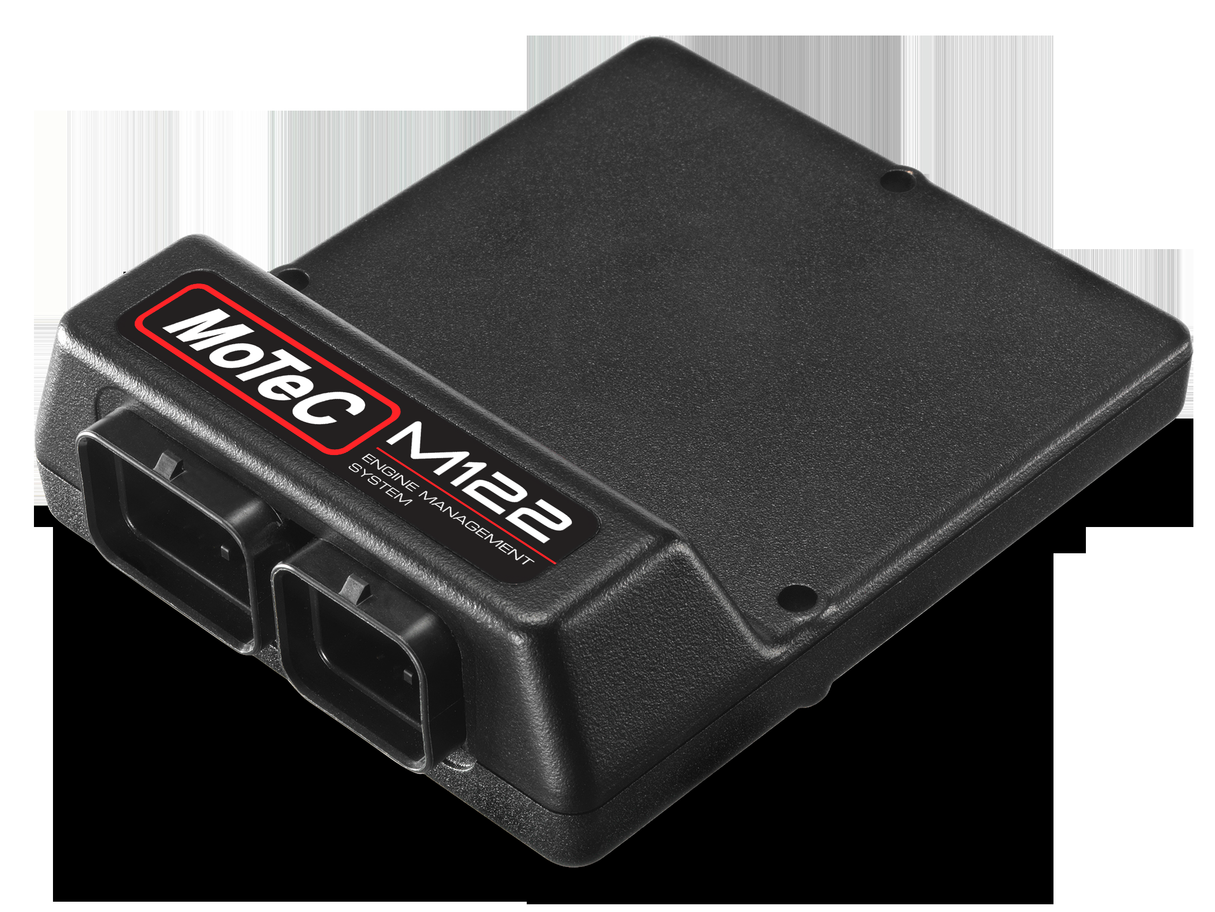
MoTeC M122 product image from the manufacturer datasheet; reproduced with permission.
MoTeC M122 is an M1-family programmable ECU, part 13122. The manufacturer identifies it for up to 4 cylinders and direct injection. M1 hardware is paired with a software package; features, channels and licences depend on the loaded package and hardware revision. MoTeC M122 product information and product image.
Identification and inputs/outputs
FieldManufacturer comparisonInjection hardware4 direct injector outputs; 6 low-side injector outputsIgnition4 low-side ignition outputsHalf-bridge outputs6Universal digital inputs7Analogue voltage / temperature inputs8 / 4CAN buses1Connector configurationtwo plastic, 60 positions
Numbers describe hardware capacity; they do not establish simultaneous availability for a specific application. MoTeC’s M1 comparison distinguishes port, inductive direct and piezo direct drivers. Check the exact injector and package; an external driver is not interchangeable with an internal driver.
Wiring and pinout
Use the M122 connector pinout and datasheet on the manufacturer product page. Connector type, keying and positions vary across M1 models; do not copy pin functions from another ECU. Verify the hardware revision, package, output allocations, wiring orientation, electrical limits and power and earth provisions against the exact unit.
Manufacturer connector tablesThese tables reproduce the complete connector position and designation lists from the MoTeC M122 datasheet. Pin identifiers are kept as printed, including letter case. Check the original connector views, mating key, wire size, electrical ratings and hardware revision before connecting. Output functions depend on the ECU package and configuration; direct-injection models require their specified drivers and precautions.Connector A — 34 positionsPinDesignationFunctionA_1OUT_HB2Half Bridge Output 2A_2SEN_5V0_ASensor 5.0V AA_3IGN_LS1Low Side Ignition 1A_4IGN_LS2Low Side Ignition 2A_5IGN_LS3Low Side Ignition 3A_6IGN_LS4Low Side Ignition 4A_7INJ_LS3Low Side Injector 3A_8INJ_LS4Low Side Injector 4A_9SEN_5V0_BSensor 5.0V BA_10BAT_NEGBattery NegativeA_11BAT_NEGBattery NegativeA_12INJ_LS5Low Side Injector 5A_13INJ_LS6Low Side Injector 6A_14AV1Analogue Voltage Input 1A_15AV2Analogue Voltage Input 2A_16AV3Analogue Voltage Input 3A_17AV4Analogue Voltage Input 4A_18OUT_HB1Half Bridge Output 1A_19INJ_D1A_POSDirect Injector 1A +A_20INJ_D1B_POSDirect Injector 1B +A_21INJ_D2A_POSDirect Injector 2A +A_22INJ_D2B_POSDirect Injector 2B +A_23INJ_LS1Low Side Injector 1A_24INJ_LS2Low Side Injector 2A_25AV5Analogue Voltage Input 5A_26BAT_POSBattery PositiveA_27INJ_D1A_NEGDirect Injector 1A -A_28INJ_D1B_NEGDirect Injector 1B -A_29INJ_D2A_NEGDirect Injector 2A -A_30INJ_D2B_NEGDirect Injector 2B -A_31OUT_HB3Half Bridge Output 3A_32OUT_HB4Half Bridge Output 4A_33OUT_HB5Half Bridge Output 5A_34OUT_HB6Half Bridge Output 6Connector B — 26 positionsPinDesignationFunctionB_1UDIG1Universal Digital Input 1B_2UDIG2Universal Digital Input 2B_3AT1Analogue Temperature Input 1B_4AT2Analogue Temperature Input 2B_5AT3Analogue Temperature Input 3B_6AT4Analogue Temperature Input 4B_7KNOCK1Knock Input 1B_8UDIG3Universal Digital Input 3B_9UDIG4Universal Digital Input 4B_10UDIG5Universal Digital Input 5B_11UDIG6Universal Digital Input 6B_12BAT_BAKBattery BackupB_13KNOCK2Knock Input 2B_14UDIG7Universal Digital Input 7B_15SEN_0V_ASensor 0V AB_16SEN_0V_BSensor 0V BB_17CAN_HICAN Bus HighB_18CAN_LOCAN Bus LowB_19SEN_6V3Sensor 6.3VB_20AV6Analogue Voltage Input 6B_21AV7Analogue Voltage Input 7B_22AV8Analogue Voltage Input 8B_23ETH_TX+Ethernet Transmit+B_24ETH_TX-Ethernet Transmit-B_25ETH_RX+Ethernet Receive+B_26ETH_RX-Ethernet Receive-
Software and context
M1 Tune configures supported packages, while M1 Build is used to develop packages. ECU and logging features depend on installed licences. MoTeC downloads; MoTeC model index.
Rendered revisions
Open each version to inspect formatting, tables and photographs.
Revision 2: MoTeC M122MoTeC M122 product image from the manufacturer datasheet; reproduced with permission.
MoTeC M122 is an M1-family programmable ECU, part 13122. The manufacturer identifies it for up to 4 cylinders and direct injection. M1 hardware is paired with a software package; features, channels and licences depend on the loaded package and hardware revision. MoTeC M122 product information and product image.
Identification and inputs/outputs
Field
Manufacturer comparison
Injection hardware
4 direct injector outputs; 6 low-side injector outputs
Ignition
4 low-side ignition outputs
Half-bridge outputs
6
Universal digital inputs
7
Analogue voltage / temperature inputs
8 / 4
CAN buses
1
Connector configuration
two plastic, 60 positions
Numbers describe hardware capacity; they do not establish simultaneous availability for a specific application. MoTeC’s M1 comparison distinguishes port, inductive direct and piezo direct drivers. Check the exact injector and package; an external driver is not interchangeable with an internal driver.
Wiring and pinout
Use the M122 connector pinout and datasheet on the manufacturer product page. Connector type, keying and positions vary across M1 models; do not copy pin functions from another ECU. Verify the hardware revision, package, output allocations, wiring orientation, electrical limits and power and earth provisions against the exact unit.
Software and context
M1 Tune configures supported packages, while M1 Build is used to develop packages. ECU and logging features depend on installed licences. MoTeC downloads; MoTeC model index.
Revision 3: MoTeC M122MoTeC M122 product image from the manufacturer datasheet; reproduced with permission.
MoTeC M122 is an M1-family programmable ECU, part 13122. The manufacturer identifies it for up to 4 cylinders and direct injection. M1 hardware is paired with a software package; features, channels and licences depend on the loaded package and hardware revision. MoTeC M122 product information and product image.
Identification and inputs/outputs
Field
Manufacturer comparison
Injection hardware
4 direct injector outputs; 6 low-side injector outputs
Ignition
4 low-side ignition outputs
Half-bridge outputs
6
Universal digital inputs
7
Analogue voltage / temperature inputs
8 / 4
CAN buses
1
Connector configuration
two plastic, 60 positions
Numbers describe hardware capacity; they do not establish simultaneous availability for a specific application. MoTeC’s M1 comparison distinguishes port, inductive direct and piezo direct drivers. Check the exact injector and package; an external driver is not interchangeable with an internal driver.
Wiring and pinout
Use the M122 connector pinout and datasheet on the manufacturer product page. Connector type, keying and positions vary across M1 models; do not copy pin functions from another ECU. Verify the hardware revision, package, output allocations, wiring orientation, electrical limits and power and earth provisions against the exact unit.
Manufacturer connector tables
These tables reproduce the complete connector position and designation lists from the MoTeC M122 datasheet. Pin identifiers are kept as printed, including letter case. Check the original connector views, mating key, wire size, electrical ratings and hardware revision before connecting. Output functions depend on the ECU package and configuration; direct-injection models require their specified drivers and precautions.
Connector A — 34 positions
Pin
Designation
Function
A_1
OUT_HB2
Half Bridge Output 2
A_2
SEN_5V0_A
Sensor 5.0V A
A_3
IGN_LS1
Low Side Ignition 1
A_4
IGN_LS2
Low Side Ignition 2
A_5
IGN_LS3
Low Side Ignition 3
A_6
IGN_LS4
Low Side Ignition 4
A_7
INJ_LS3
Low Side Injector 3
A_8
INJ_LS4
Low Side Injector 4
A_9
SEN_5V0_B
Sensor 5.0V B
A_10
BAT_NEG
Battery Negative
A_11
BAT_NEG
Battery Negative
A_12
INJ_LS5
Low Side Injector 5
A_13
INJ_LS6
Low Side Injector 6
A_14
AV1
Analogue Voltage Input 1
A_15
AV2
Analogue Voltage Input 2
A_16
AV3
Analogue Voltage Input 3
A_17
AV4
Analogue Voltage Input 4
A_18
OUT_HB1
Half Bridge Output 1
A_19
INJ_D1A_POS
Direct Injector 1A +
A_20
INJ_D1B_POS
Direct Injector 1B +
A_21
INJ_D2A_POS
Direct Injector 2A +
A_22
INJ_D2B_POS
Direct Injector 2B +
A_23
INJ_LS1
Low Side Injector 1
A_24
INJ_LS2
Low Side Injector 2
A_25
AV5
Analogue Voltage Input 5
A_26
BAT_POS
Battery Positive
A_27
INJ_D1A_NEG
Direct Injector 1A -
A_28
INJ_D1B_NEG
Direct Injector 1B -
A_29
INJ_D2A_NEG
Direct Injector 2A -
A_30
INJ_D2B_NEG
Direct Injector 2B -
A_31
OUT_HB3
Half Bridge Output 3
A_32
OUT_HB4
Half Bridge Output 4
A_33
OUT_HB5
Half Bridge Output 5
A_34
OUT_HB6
Half Bridge Output 6
Connector B — 26 positions
Pin
Designation
Function
B_1
UDIG1
Universal Digital Input 1
B_2
UDIG2
Universal Digital Input 2
B_3
AT1
Analogue Temperature Input 1
B_4
AT2
Analogue Temperature Input 2
B_5
AT3
Analogue Temperature Input 3
B_6
AT4
Analogue Temperature Input 4
B_7
KNOCK1
Knock Input 1
B_8
UDIG3
Universal Digital Input 3
B_9
UDIG4
Universal Digital Input 4
B_10
UDIG5
Universal Digital Input 5
B_11
UDIG6
Universal Digital Input 6
B_12
BAT_BAK
Battery Backup
B_13
KNOCK2
Knock Input 2
B_14
UDIG7
Universal Digital Input 7
B_15
SEN_0V_A
Sensor 0V A
B_16
SEN_0V_B
Sensor 0V B
B_17
CAN_HI
CAN Bus High
B_18
CAN_LO
CAN Bus Low
B_19
SEN_6V3
Sensor 6.3V
B_20
AV6
Analogue Voltage Input 6
B_21
AV7
Analogue Voltage Input 7
B_22
AV8
Analogue Voltage Input 8
B_23
ETH_TX+
Ethernet Transmit+
B_24
ETH_TX-
Ethernet Transmit-
B_25
ETH_RX+
Ethernet Receive+
B_26
ETH_RX-
Ethernet Receive-
Software and context
M1 Tune configures supported packages, while M1 Build is used to develop packages. ECU and logging features depend on installed licences. MoTeC downloads; MoTeC model index.