Removed text is struck through; added text is highlighted.
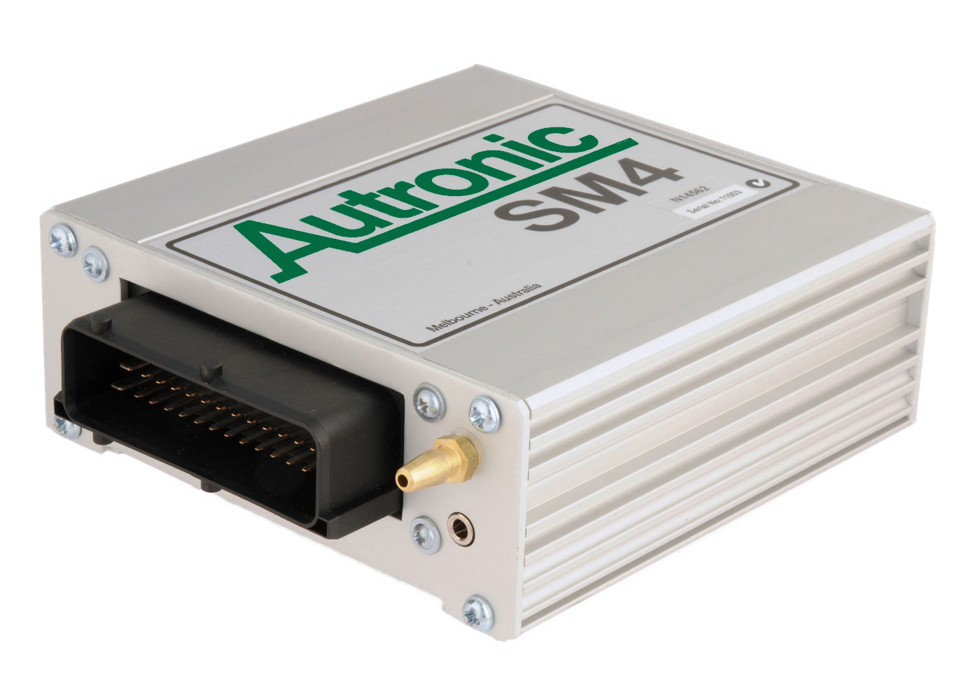
Autronic sm4 manufacturer product image: Autronic; reproduced with permission.
Autronic SM4 is a standalone or earlier programmable engine-management system. SM4 is a third-generation engine ECU with eight injector outputs, four ignition outputs and selectable peak-and-hold injector groups. Model-specific information.
Autronic's product data describes a 16-bit Intel processor running at 20 MHz, a single 42-way main connector, a 3.5 mm stereo-jack serial port and an anodised aluminium case of 130 × 124 × 48 mm. Dual-calibration (SM4DC) and marine (SM4MR) versions share the standard loom; on SM4DC units pin 39 is the calibration select input.
Identification and features
Record the ECU label, model, part number, hardware revision, firmware, configured injectors, ignition hardware and loom before comparing systems. Some outputs can be reassigned; hardware, software, current limits and engine-specific options determine what is actually available.
ProcessorManufacturer documentation states only that the SM4 uses a 16-bit Intel microcontroller at 20 MHz; the exact device and memory parts are not named. The unit is specified for 12–15 V operation (6.2–18 V continuous operating limits) and −40 to +85 °C. Autronic SM4 product data.Engine applicationsThe SM4 is a universal standalone ECU rather than a plug-in for a particular vehicle. Autronic lists support for 1 to 8, 10, 12, 14 and 16-cylinder engines, two-stroke and four-stroke cycles, and two-rotor rotary engines. Injection is fully sequential up to eight cylinders and semi-sequential above that. Ignition can drive distributor, distributorless, coil-on-plug and capacitor-discharge systems through four push-pull outputs.Four-stroke cylindersMaximum speed (manufacturer)1–428,000 rpm5–618,000 rpm7–814,000 rpm10–1612,000 rpmInjector drivers are arranged as two groups of four, each selectable at 4 A/1 A or 2 A/0.5 A peak/hold for coil resistances of 0.6–16 Ω; an 8 A/2 A high-current build is available to special order. Autronic states the SM4 is intended for motorsport, that road-legal compliance is not guaranteed, and that it must not be used to control engines in manned aircraft.
SM4 connector positions
Manufacturer function table, Autronic product data. Use the original connector drawing for orientation and output limitations. On dual-calibration versions pin 39 selects calibration rather than HSI3. Outputs may have shared alternate functions.
Connector pinoutThe Autronic SM4 connector pinout page gives an interactive, redrawn wire-side diagram of the 42-way connector, with the manufacturer's current and frequency limits and the standard Autronic loom wire colour for every pin. It is based on the Autronic pin-function table (12 October 2016) and the SM4 Wiring Basic drawing (revision 3.4, 23 September 2014), both manufacturer documents. Diagram redrawn by Tuning Wiki from the Autronic SM4 Wiring Basic drawing.
Wiring and pinout
Consult the Autronic SM4 wiring and documentation source and identify the exact connector face, part and version. Do not apply wiring from a similarly named model. If an exact drawing is unavailable for the unit at hand, obtain it from the manufacturer or supplier before making connections.
Further information
Autronic SM4 model informationWiring, manuals or technical archiveAutronic manufacturer index
Not establishedThe exact Intel microcontroller part, the connector housing manufacturer and part number, and the physical cavity spacing are not given in the cited Autronic documents.SourcesSM4 ECU. Autronic (Aubert Electronics), manufacturer product and specification page. Accessed 19 November 2026.Autronic SM4 – Input / Output Pin Functions. Autronic, manufacturer pin-function table, 12 October 2016. Accessed 19 November 2026.SM4 Wiring Basic. Aubert Electronics Pty Ltd, manufacturer wiring diagram SM4_0001, revision 3.4, 23 September 2014; connector shown from the wire side. Accessed 19 November 2026.Wiring diagrams. Autronic, manufacturer download index. Accessed 19 November 2026.
Rendered revisions
Open each version to inspect formatting, tables and photographs.
Revision 2: Autronic SM4Autronic sm4 manufacturer product image: Autronic; reproduced with permission.
Autronic SM4 is a standalone or earlier programmable engine-management system. SM4 is a third-generation engine ECU with eight injector outputs, four ignition outputs and selectable peak-and-hold injector groups. Model-specific information.
Identification and features
Record the ECU label, model, part number, hardware revision, firmware, configured injectors, ignition hardware and loom before comparing systems. Some outputs can be reassigned; hardware, software, current limits and engine-specific options determine what is actually available.
SM4 connector positions
Manufacturer function table, Autronic product data. Use the original connector drawing for orientation and output limitations. On dual-calibration versions pin 39 selects calibration rather than HSI3. Outputs may have shared alternate functions.
Pin
Function
1
Ignition switch input
2
Injector 8 / switch 3
3
Injector 7 / switch 2
4
Injector 5
5
Ignition 1
6
Ignition 2
7
Output 1
8
Analogue 1
9
Coolant temperature
10
HSI 1
11
+8 V trigger supply
12
Output 8 / tacho
13
Output 6
14
PWM 2
15
+12 V main supply
16
Injector 4
17
Injector 1
18
Injector 6 / switch 1
19
Ignition 3
20
Output 3
21
Throttle position
22
Signal ground
23
Air temperature
24
HSI 2
25
Cylinder +
26
Sync +
27
Output 5
28
PWM 1
29
Power ground
30
+12 V RAM supply
31
Injector 3
32
Injector 2
33
Ignition 4
34
Output 2
35
Output 4
36
+5 V sensor supply
37
Oxygen input
38
Analogue 2
39
HSI 3 / dual-calibration select
40
Cylinder -
41
Sync -
42
Output 7
Wiring and pinout
Consult the Autronic SM4 wiring and documentation source and identify the exact connector face, part and version. Do not apply wiring from a similarly named model. If an exact drawing is unavailable for the unit at hand, obtain it from the manufacturer or supplier before making connections.
Revision 3: Autronic SM4Autronic sm4 manufacturer product image: Autronic; reproduced with permission.
Autronic SM4 is a standalone or earlier programmable engine-management system. SM4 is a third-generation engine ECU with eight injector outputs, four ignition outputs and selectable peak-and-hold injector groups. Model-specific information.
Autronic's product data describes a 16-bit Intel processor running at 20 MHz, a single 42-way main connector, a 3.5 mm stereo-jack serial port and an anodised aluminium case of 130 × 124 × 48 mm. Dual-calibration (SM4DC) and marine (SM4MR) versions share the standard loom; on SM4DC units pin 39 is the calibration select input.
Identification and features
Record the ECU label, model, part number, hardware revision, firmware, configured injectors, ignition hardware and loom before comparing systems. Some outputs can be reassigned; hardware, software, current limits and engine-specific options determine what is actually available.
Processor
Manufacturer documentation states only that the SM4 uses a 16-bit Intel microcontroller at 20 MHz; the exact device and memory parts are not named. The unit is specified for 12–15 V operation (6.2–18 V continuous operating limits) and −40 to +85 °C. Autronic SM4 product data.
Engine applications
The SM4 is a universal standalone ECU rather than a plug-in for a particular vehicle. Autronic lists support for 1 to 8, 10, 12, 14 and 16-cylinder engines, two-stroke and four-stroke cycles, and two-rotor rotary engines. Injection is fully sequential up to eight cylinders and semi-sequential above that. Ignition can drive distributor, distributorless, coil-on-plug and capacitor-discharge systems through four push-pull outputs.
Four-stroke cylinders
Maximum speed (manufacturer)
1–4
28,000 rpm
5–6
18,000 rpm
7–8
14,000 rpm
10–16
12,000 rpm
Injector drivers are arranged as two groups of four, each selectable at 4 A/1 A or 2 A/0.5 A peak/hold for coil resistances of 0.6–16 Ω; an 8 A/2 A high-current build is available to special order. Autronic states the SM4 is intended for motorsport, that road-legal compliance is not guaranteed, and that it must not be used to control engines in manned aircraft.
SM4 connector positions
Manufacturer function table, Autronic product data. Use the original connector drawing for orientation and output limitations. On dual-calibration versions pin 39 selects calibration rather than HSI3. Outputs may have shared alternate functions.
Pin
Function
1
Ignition switch input
2
Injector 8 / switch 3
3
Injector 7 / switch 2
4
Injector 5
5
Ignition 1
6
Ignition 2
7
Output 1
8
Analogue 1
9
Coolant temperature
10
HSI 1
11
+8 V trigger supply
12
Output 8 / tacho
13
Output 6
14
PWM 2
15
+12 V main supply
16
Injector 4
17
Injector 1
18
Injector 6 / switch 1
19
Ignition 3
20
Output 3
21
Throttle position
22
Signal ground
23
Air temperature
24
HSI 2
25
Cylinder +
26
Sync +
27
Output 5
28
PWM 1
29
Power ground
30
+12 V RAM supply
31
Injector 3
32
Injector 2
33
Ignition 4
34
Output 2
35
Output 4
36
+5 V sensor supply
37
Oxygen input
38
Analogue 2
39
HSI 3 / dual-calibration select
40
Cylinder -
41
Sync -
42
Output 7
Connector pinout
The Autronic SM4 connector pinout page gives an interactive, redrawn wire-side diagram of the 42-way connector, with the manufacturer's current and frequency limits and the standard Autronic loom wire colour for every pin. It is based on the Autronic pin-function table (12 October 2016) and the SM4 Wiring Basic drawing (revision 3.4, 23 September 2014), both manufacturer documents. Diagram redrawn by Tuning Wiki from the Autronic SM4 Wiring Basic drawing.
Wiring and pinout
Consult the Autronic SM4 wiring and documentation source and identify the exact connector face, part and version. Do not apply wiring from a similarly named model. If an exact drawing is unavailable for the unit at hand, obtain it from the manufacturer or supplier before making connections.
The exact Intel microcontroller part, the connector housing manufacturer and part number, and the physical cavity spacing are not given in the cited Autronic documents.
Sources
SM4 ECU. Autronic (Aubert Electronics), manufacturer product and specification page. Accessed 19 November 2026.