Removed text is struck through; added text is highlighted.
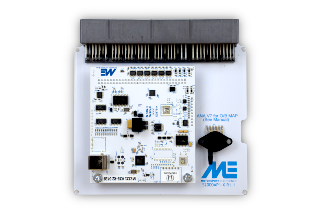
ME221 Honda S2000 AP1 plug-in ECU. Manufacturer product image: Motorsport Electronics; used with permission.
ME221 plug-in ECU for Honda S2000 AP1. This application-specific unit replaces the factory ECU electronics while using the vehicle's original harness connector, subject to exact fitment and configuration. Motorsport Electronics product information · application installation guide.
Identification and application
ME's installation guide identifies Honda S2000 AP1 2000–05, whereas the product page describes 2000–04. Check the particular ECU and market rather than relying on year alone. Record the serial, board version, firmware, factory ECU part number, engine and transmission before installing. The ME221 and ME442 are separate hardware choices; the manufacturer lists wideband, onboard logging and EGT as ME442 plug-in features. Optional electronic throttle equipment and supported functions vary by board and configuration. See ME's model comparison and downloads.
Connector and pinout
Use the OEM header and auxiliary connector diagrams in the exact application installation guide. Connector view, jumper/switch settings, sensors and supported functions vary by generation and vehicle. The universal 28-way and 90-way wire-in tables do not define this plug-in board's factory header.
Software and installation
Use the correct MEITE / EZ Tune release and the model-specific firmware and base map. The installation guide covers sensor settings, baseline checks, expansion, jumper settings and any vehicle-specific exceptions; a base map still needs calibration and verification on the actual engine. See the ME221 family page for wire-in generation and hardware context.
Sources reviewed 17 November 2026.
Manufacturer S2000 connector schedulesThese are the positions explicitly listed in Appendix A of the manufacturer’s ME221/ME442 S2000 AP1 Gen1 and Gen2/2B installation guide. The two I/O columns reflect the guide’s distinct board generations. A dash or “not specified” preserves the source’s missing entry; it does not establish that a cavity is unconnected. The actual model, generation, DBW hardware and firmware determine available functions. The guide identifies the D connector as TE 179678-6.PinVehicle / connector functionGEN1 I/OGEN2 / GEN2B I/OA1Coolant dashboard gaugeLS10LS 3A2Air control valvedrvSLS7LS 7A3EVAP bypass solenoid ventdrvSLS8LS 16A4EVAP canister ventLS 2LS 8A6EVAP purgeLS 1LS 4A9VSSHS DIGIN 1DIGIN 4A12Immobiliser indicator lightdrvSLS4LS 17A15Fuel pump relaydrvSLS1LS 11A17AC clutch relaydrvSLS5LS 14A18CEL lightdrvSLS2LS 13A19Tacho outputTACHOTACHOA20Primary radiator fandrvSLS3LS 15A27AC switch signaldrvDIGIN3DIGIN 5A28Air pump relaydrvSLS6LS 18A29Fuel tank pressure sensorANAV 6ANAV 6A30Electronic load detectorANAV 9ANAV 5B1Switched 12 V ignition12VIGN12VIGNB3Injector 2LS 5Injector 2B4Injector 3LS 6Injector 3B5Injector 4LS 7Injector 4B11Injector 1LS 4Injector 1B12VTEC solenoidLS 12COIL 5B14Spare low-side 9 A driverLS 11LS 1B15Spare low-side 9 A driverLS 9LS 2B23Idle control valveLS 3LS 9C3Knock sensor positiveKnock 1Not specifiedC4Ignition coil 1COIL ACoil 1C8Crank signal positiveNot specifiedNot specifiedC9Crank signal negativeNot specifiedNot specifiedC12Ignition coil 2COIL BCoil 2C13Ignition coil 3COIL CCoil 3C14Ignition coil 4COIL DCoil 4C15O2 signal 2ANA-V7—C16O2 signal 1ANA-V3AnaV 3C17MAP signalANA-V1 (OEM MAP)OEM MAP ANAV1; on-board 4 bar ANAV4C20/C21Cam positive / cam negativeNot specifiedNot specifiedC22Knock sensor negativeNot specifiedNot specifiedC25Intake air temperature signalANA-T1ANAT 1C26Coolant sensor signalANA-T2ANAT 2C27Throttle position signalANA-V2ANAV 2D1GEN1 digital input / GEN2 injectordrvDIGIN1Injector 5D2GEN1 digital input / GEN2 injectordrvDIGIN2Injector 6D3GEN2 spare low side—Injector 7D4GEN1 digital input / GEN2 injectordrvDIGIN4Injector 8D5GEN2 spare analogue input—ANAT 3D6GEN2 spare analogue input—ANAT 4D7GEN2 DBW HBA 1—DBW HBA 1D8GEN2 DBW HBA 2drvDIGIN5DBW HBA 2D9GEN2 low side—LS 10D10GEN1 analogue input / GEN2 EGTAna-V8EGT signalD11CAN bus lowCANBusCANBusD12CAN bus highCANBusCANBusD135 V low-current sensor supply5V5VD14Sensor groundGNDGNDThe guide groups C20/C21 as cam positive / cam negative; verify the actual polarity and connector view with the manufacturer drawing and vehicle loom. It also labels D8 as GEN2 DBW HBA 2 while listing a GEN1 digital input in the adjacent column; the original wording is preserved.The guide assigns GEN1 LS7 to both A2 and B4. It does not explain that repeated label; verify the board and configuration with Motorsport Electronics before treating these as independent outputs.Structured connector pinoutEvery cavity of the factory A, B, C and D connectors, with the manufacturer's assignments and GEN1/GEN2 channel mapping, is drawn in Motorsport Electronics ME221 and ME442 Honda S2000 AP1 plug-in connector pinout.ProcessorMotorsport Electronics does not publish the microcontroller part number. A distributor specification sheet for the ME221 lists a 120 MHz 32-bit RISC processor; this is a vendor specification rather than a component identification. ATP Turbo ME221 specification sheet (May 2023), accessed 19 November 2026.
Rendered revisions
Open each version to inspect formatting, tables and photographs.
ME's installation guide identifies Honda S2000 AP1 2000–05, whereas the product page describes 2000–04. Check the particular ECU and market rather than relying on year alone. Record the serial, board version, firmware, factory ECU part number, engine and transmission before installing. The ME221 and ME442 are separate hardware choices; the manufacturer lists wideband, onboard logging and EGT as ME442 plug-in features. Optional electronic throttle equipment and supported functions vary by board and configuration. See ME's model comparison and downloads.
Connector and pinout
Use the OEM header and auxiliary connector diagrams in the exact application installation guide. Connector view, jumper/switch settings, sensors and supported functions vary by generation and vehicle. The universal 28-way and 90-way wire-in tables do not define this plug-in board's factory header.
Software and installation
Use the correct MEITE / EZ Tune release and the model-specific firmware and base map. The installation guide covers sensor settings, baseline checks, expansion, jumper settings and any vehicle-specific exceptions; a base map still needs calibration and verification on the actual engine. See the ME221 family page for wire-in generation and hardware context.
Sources reviewed 17 November 2026.
Revision 5: Motorsport Electronics ME221 Honda S2000 AP1 plug-inME221 Honda S2000 AP1 plug-in ECU. Manufacturer product image: Motorsport Electronics; used with permission.
ME's installation guide identifies Honda S2000 AP1 2000–05, whereas the product page describes 2000–04. Check the particular ECU and market rather than relying on year alone. Record the serial, board version, firmware, factory ECU part number, engine and transmission before installing. The ME221 and ME442 are separate hardware choices; the manufacturer lists wideband, onboard logging and EGT as ME442 plug-in features. Optional electronic throttle equipment and supported functions vary by board and configuration. See ME's model comparison and downloads.
Connector and pinout
Use the OEM header and auxiliary connector diagrams in the exact application installation guide. Connector view, jumper/switch settings, sensors and supported functions vary by generation and vehicle. The universal 28-way and 90-way wire-in tables do not define this plug-in board's factory header.
Software and installation
Use the correct MEITE / EZ Tune release and the model-specific firmware and base map. The installation guide covers sensor settings, baseline checks, expansion, jumper settings and any vehicle-specific exceptions; a base map still needs calibration and verification on the actual engine. See the ME221 family page for wire-in generation and hardware context.
Sources reviewed 17 November 2026.
Manufacturer S2000 connector schedules
These are the positions explicitly listed in Appendix A of the manufacturer’s ME221/ME442 S2000 AP1 Gen1 and Gen2/2B installation guide. The two I/O columns reflect the guide’s distinct board generations. A dash or “not specified” preserves the source’s missing entry; it does not establish that a cavity is unconnected. The actual model, generation, DBW hardware and firmware determine available functions. The guide identifies the D connector as TE 179678-6.
Pin
Vehicle / connector function
GEN1 I/O
GEN2 / GEN2B I/O
A1
Coolant dashboard gauge
LS10
LS 3
A2
Air control valve
drvSLS7
LS 7
A3
EVAP bypass solenoid vent
drvSLS8
LS 16
A4
EVAP canister vent
LS 2
LS 8
A6
EVAP purge
LS 1
LS 4
A9
VSS
HS DIGIN 1
DIGIN 4
A12
Immobiliser indicator light
drvSLS4
LS 17
A15
Fuel pump relay
drvSLS1
LS 11
A17
AC clutch relay
drvSLS5
LS 14
A18
CEL light
drvSLS2
LS 13
A19
Tacho output
TACHO
TACHO
A20
Primary radiator fan
drvSLS3
LS 15
A27
AC switch signal
drvDIGIN3
DIGIN 5
A28
Air pump relay
drvSLS6
LS 18
A29
Fuel tank pressure sensor
ANAV 6
ANAV 6
A30
Electronic load detector
ANAV 9
ANAV 5
B1
Switched 12 V ignition
12VIGN
12VIGN
B3
Injector 2
LS 5
Injector 2
B4
Injector 3
LS 6
Injector 3
B5
Injector 4
LS 7
Injector 4
B11
Injector 1
LS 4
Injector 1
B12
VTEC solenoid
LS 12
COIL 5
B14
Spare low-side 9 A driver
LS 11
LS 1
B15
Spare low-side 9 A driver
LS 9
LS 2
B23
Idle control valve
LS 3
LS 9
C3
Knock sensor positive
Knock 1
Not specified
C4
Ignition coil 1
COIL A
Coil 1
C8
Crank signal positive
Not specified
Not specified
C9
Crank signal negative
Not specified
Not specified
C12
Ignition coil 2
COIL B
Coil 2
C13
Ignition coil 3
COIL C
Coil 3
C14
Ignition coil 4
COIL D
Coil 4
C15
O2 signal 2
ANA-V7
—
C16
O2 signal 1
ANA-V3
AnaV 3
C17
MAP signal
ANA-V1 (OEM MAP)
OEM MAP ANAV1; on-board 4 bar ANAV4
C20/C21
Cam positive / cam negative
Not specified
Not specified
C22
Knock sensor negative
Not specified
Not specified
C25
Intake air temperature signal
ANA-T1
ANAT 1
C26
Coolant sensor signal
ANA-T2
ANAT 2
C27
Throttle position signal
ANA-V2
ANAV 2
D1
GEN1 digital input / GEN2 injector
drvDIGIN1
Injector 5
D2
GEN1 digital input / GEN2 injector
drvDIGIN2
Injector 6
D3
GEN2 spare low side
—
Injector 7
D4
GEN1 digital input / GEN2 injector
drvDIGIN4
Injector 8
D5
GEN2 spare analogue input
—
ANAT 3
D6
GEN2 spare analogue input
—
ANAT 4
D7
GEN2 DBW HBA 1
—
DBW HBA 1
D8
GEN2 DBW HBA 2
drvDIGIN5
DBW HBA 2
D9
GEN2 low side
—
LS 10
D10
GEN1 analogue input / GEN2 EGT
Ana-V8
EGT signal
D11
CAN bus low
CANBus
CANBus
D12
CAN bus high
CANBus
CANBus
D13
5 V low-current sensor supply
5V
5V
D14
Sensor ground
GND
GND
The guide groups C20/C21 as cam positive / cam negative; verify the actual polarity and connector view with the manufacturer drawing and vehicle loom. It also labels D8 as GEN2 DBW HBA 2 while listing a GEN1 digital input in the adjacent column; the original wording is preserved.
The guide assigns GEN1 LS7 to both A2 and B4. It does not explain that repeated label; verify the board and configuration with Motorsport Electronics before treating these as independent outputs.
Motorsport Electronics does not publish the microcontroller part number. A distributor specification sheet for the ME221 lists a 120 MHz 32-bit RISC processor; this is a vendor specification rather than a component identification. ATP Turbo ME221 specification sheet (May 2023), accessed 19 November 2026.