Removed text is struck through; added text is highlighted.
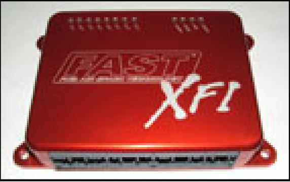
Original FAST XFI user-tunable fuel and ignition ECU, preceding the XFI 2.0 software upgrade.
Identification and functions
The original XFI installation manual documents the main harness, crank/cam interfaces and ECU connector charts. It identifies A3 and A4 as inductive cam and crank positive inputs and A7/A8 as discrete cam/crank inputs; confirm returns, shield, terminal orientation and the exact harness in the source. FAST states that original XFI units may be eligible for a version 2.0 firmware upgrade; verify serial and configuration before proceeding.
Wiring and support
Identify ECU part number, software version, harness and engine before connecting inputs or outputs. Exact pin functions depend on the specific unit, harness and optional drivers. FAST's software and documentation index separates its families. A missing pinout is not evidence that a related system uses the same connector.
See the FAST manufacturer index. Sources reviewed 17 November 2026.
Manufacturer connector schedulesThe following schedule is from the original XFI installation guide; the guide also includes the FAST 301100 main harness drawing. The FAST XFI installation manual, PDF pages 14–16 and the 301100 harness schematic on page 164, lists 32 A, 25 B, 31 C and 16 D positions. Asterisks reproduce the manual chart's high-current pin notation; the chart marks A25 with an asterisk while the 301100 schematic does not. Confirm the actual connector and terminal size. A dash denotes a blank colour in the source, not an unused circuit. Harness colours and downstream connector letters can vary with the loom. Identify connector orientation and hardware before wiring.ECU connector AECU pinDocumented functionHarness wire colourA1*Inductive Cam Pickup Return (Ground)BlackA2*Inductive Crank Pickup Return (Ground)BlackA3Inductive Cam Positive Input SignalRedA4Inductive Crank Positive Input SignalRedA5Discrete Vehicle Speed Sensor Input SignalWhite (B)A6Discrete Auxiliary Speed Sensor Input SignalOrange (B)A7Discrete Cam Pickup Input SignalYlw / Blk (C )A8Discrete Crank Pickup Input SignalBrn / Wht (F)A9Knock Input Signal (ESC)Black (C)A10TFI / EDIS Ignition Output (TFI/SAW)Blu / Wht (H)A11Points Ignition Output (POINTS)WhiteA12*Main Power Return (Ground)Black (10 ga)A13*Distributor Return (Ground)Blk / Wht (D)A14HEI Ignition Output (EST)Tan / Blk (E)A15Crank / Run Mode Output (BYPASS)Grn / Lt Grn (G )A16Inductive Vehicle Speed Sensor Positive Input SignalYellow (C )A17Inductive Auxiliary Speed Sensor Positive Input SignalViolet (D)A18Pulse Width Modulated (PWM) Output #2—A19Pulse Width Modulated (PWM) Output #1—A20Clutch Input Signal—A21Flash Programming Enable Input SignalBlue (A)A22Calibration Select Switch Input #1Gray (B)A23Calibration Select Switch Input #0Yellow (C )A24A/C Idle Increase Input Signal—A25*Digital Auxiliary Input Signal #0—A26Digital Auxiliary Input Signal #1—A27Digital Auxiliary Input Signal #2—A28Digital Auxiliary Input Signal #3—A29Digital Auxiliary Input Signal #4—A30Digital Auxiliary Input Signal #5—A31Digital Auxiliary Input Signal #6—A32Digital Auxiliary Input Signal #7—ECU connector BECU pinDocumented functionHarness wire colourB1Auxiliary Switched Output #1—B2Auxiliary Switched Output #2—B3Auxiliary Switched Output #3—B4Auxiliary Switched Output #4—B5Fuel Pump Control OutputBlackB6Torque Converter Clutch (TCC) Control Output—B7*Main Power Return (Ground)Black 10gageB8*Digital Inputs Return (Ground)BlackB9Service Engine Soon (SES) Lamp OutputLt Green (D)B10Fan Control OutputBlackB11A/C Enable Output—B12Idle Air Control (IAC) Output A HiRed (A)B13Idle Air Control (IAC) Output A LoBlue (B)B14Idle Air Control (IAC) Output B HiYlw (C )B15Idle Air Control (IAC) Output B LoBlack (D)B16Power Adder Hold Enable InputPink (E)B17*Switched Ignition Voltage InputPink (Sw Ign)B18*Battery Voltage InputRed (Batt 3 Amp)B19Power Adder Enable InputPink (F)B20Power Adder Switched Output #1Blu / Wht (A)B21Power Adder Switched Output #2Blu / Ylw (B)B22Power Adder Switched Output #3Blu / Grn (C )B23Power Adder Switched Output #4Blu / Orn (D)B24*Analog Inputs Return (Ground)BlackB25*Main Power Return (Ground)BlackECU connector CECU pinDocumented functionHarness wire colourC1UEGOP+White (B)C2UEGOP-Black (A)C3UEGOS+Red (C )C4UEGOR+Gray (E)C5UEGOR-Blue (F)C6UEGOH-Yellow (G)C7Pulse Width Modulated (PWM) Output #3 (EGR Control)—C8Pulse Width Modulated (PWM) Output #4 (Boost Control)BrownC9Controller Area Network (CAN) #1 High Signal—C10Controller Area Network (CAN) #1 Low Signal—C11Analog Auxiliary Input Return (Ground)Black (K)C12Analog Auxiliary Input Signal #1Blu / Gra (A)C13Analog Auxiliary Input Signal #2Gray (B)C14Analog Auxiliary Input Signal #3Violet(C )C15Analog Auxiliary Input Signal #4Lt Green (D)C16Analog Auxiliary Input Signal #5Ylw / Blk (E)C17Analog Auxiliary Input Signal #6Blue (F)C18Analog Auxiliary Input Signal #7Brn / Wht (G)C19Analog Auxiliary Input Signal #8White (H)C20Manifold Absolute Pressure (MAP) Sensor Input SignalWht / Vio (B)C21Throttle Position Sensor (TPS) Input SignalWht / Red (B)C22Air Temp Sensor (ATS) Input SignalWht / Pnk (A)C23Coolant Temperature Sensor (CTS) Input SignalWhite (A)C245 Volt Reference OutputRed (5 volt ref)C25Controller Area Network (CAN) #0 High Signal—C26Controller Area Network (CAN) #0 Low Signal—C27RS-232 PC Communications Transmit #0Red (A)C28RS-232 PC Communications Receive #0Black (C)C29RS-232 Communications Return (Ground)White (B)C30RS-232 PC Communications Transmit #1—C31RS-232 PC Communications Receive #1—ECU connector DECU pinDocumented functionHarness wire colourD1*Main Power Return (Ground)Black (10ga)D2Injector Output ABlack (A)D3Main Power Return (Ground)—D4Injector Output BBrown (B)D5Main Power Return (Ground)—D6*Main Power Return (Ground)—D7Injector Output CYellow (C)D8Main Power Return (Ground)—D9Injector Output DGreen (D)D10Main Power Return (Ground)—D11Injector Output EOrange (E)D12Main Power Return (Ground)—D13Injector Output FBlue (F)D14Injector Output GGray (G)D15Main Power Return (Ground)—D16Injector Output HViolet (H)Original FAST XFI ECU, as illustrated in the FAST XFI installation manual, PDF page 3. Manufacturer photograph reproduced with permission.
Rendered revisions
Open each version to inspect formatting, tables and photographs.
Revision 1: FAST XFI
Original FAST XFI user-tunable fuel and ignition ECU, preceding the XFI 2.0 software upgrade.
Identification and functions
The original XFI installation manual documents the main harness, crank/cam interfaces and ECU connector charts. It identifies A3 and A4 as inductive cam and crank positive inputs and A7/A8 as discrete cam/crank inputs; confirm returns, shield, terminal orientation and the exact harness in the source. FAST states that original XFI units may be eligible for a version 2.0 firmware upgrade; verify serial and configuration before proceeding.
Wiring and support
Identify ECU part number, software version, harness and engine before connecting inputs or outputs. Exact pin functions depend on the specific unit, harness and optional drivers. FAST's software and documentation index separates its families. A missing pinout is not evidence that a related system uses the same connector.
Original FAST XFI user-tunable fuel and ignition ECU, preceding the XFI 2.0 software upgrade.
Identification and functions
The original XFI installation manual documents the main harness, crank/cam interfaces and ECU connector charts. It identifies A3 and A4 as inductive cam and crank positive inputs and A7/A8 as discrete cam/crank inputs; confirm returns, shield, terminal orientation and the exact harness in the source. FAST states that original XFI units may be eligible for a version 2.0 firmware upgrade; verify serial and configuration before proceeding.
Wiring and support
Identify ECU part number, software version, harness and engine before connecting inputs or outputs. Exact pin functions depend on the specific unit, harness and optional drivers. FAST's software and documentation index separates its families. A missing pinout is not evidence that a related system uses the same connector.
The following schedule is from the original XFI installation guide; the guide also includes the FAST 301100 main harness drawing. The FAST XFI installation manual, PDF pages 14–16 and the 301100 harness schematic on page 164, lists 32 A, 25 B, 31 C and 16 D positions. Asterisks reproduce the manual chart's high-current pin notation; the chart marks A25 with an asterisk while the 301100 schematic does not. Confirm the actual connector and terminal size. A dash denotes a blank colour in the source, not an unused circuit. Harness colours and downstream connector letters can vary with the loom. Identify connector orientation and hardware before wiring.
ECU connector A
ECU pin
Documented function
Harness wire colour
A1*
Inductive Cam Pickup Return (Ground)
Black
A2*
Inductive Crank Pickup Return (Ground)
Black
A3
Inductive Cam Positive Input Signal
Red
A4
Inductive Crank Positive Input Signal
Red
A5
Discrete Vehicle Speed Sensor Input Signal
White (B)
A6
Discrete Auxiliary Speed Sensor Input Signal
Orange (B)
A7
Discrete Cam Pickup Input Signal
Ylw / Blk (C )
A8
Discrete Crank Pickup Input Signal
Brn / Wht (F)
A9
Knock Input Signal (ESC)
Black (C)
A10
TFI / EDIS Ignition Output (TFI/SAW)
Blu / Wht (H)
A11
Points Ignition Output (POINTS)
White
A12*
Main Power Return (Ground)
Black (10 ga)
A13*
Distributor Return (Ground)
Blk / Wht (D)
A14
HEI Ignition Output (EST)
Tan / Blk (E)
A15
Crank / Run Mode Output (BYPASS)
Grn / Lt Grn (G )
A16
Inductive Vehicle Speed Sensor Positive Input Signal
Yellow (C )
A17
Inductive Auxiliary Speed Sensor Positive Input Signal